This thread has been locked.

If you have a related question, please click the "Ask a related question" button in the top right corner. The newly created question will be automatically linked to this question.

TLV7044: propagation delay problem

Part Number: TLV7044

Hi everyone.
I'm making a circuit that uses the TLV7044 chip.
I have a question about the propagation delay parameter.
The tlv7044 has a propagation delay of 3 usec.
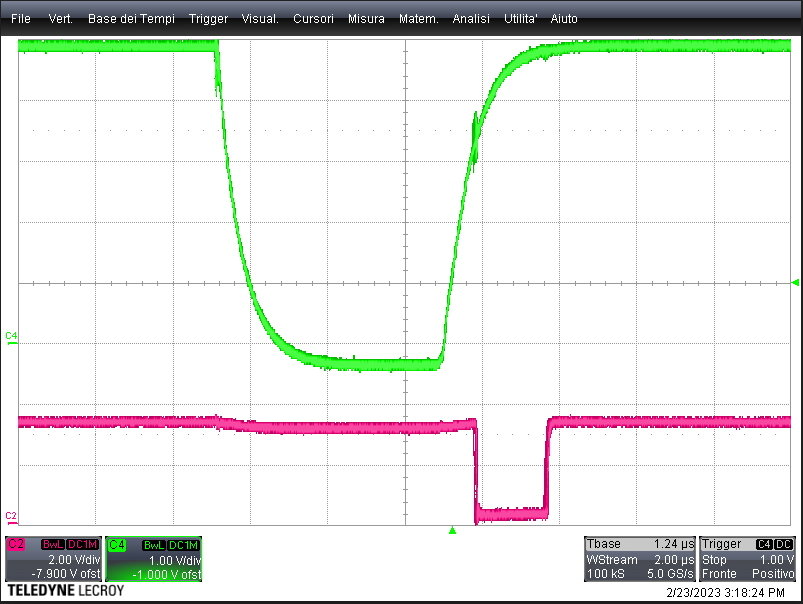
If on the inputs of the comparator i had a differential pulse that lasts less than 3 usec, would it still propagate to the output?
For example, if the non-inverting input were fixed at +1volt (vref) and on the inverting input there was a direct voltage of 4V which goes to 0volt for only 500nsec 
and then returns to 4V, I would be able to see the pulse in the output?
Best regards,
Luca.
  • Hello Luca,

    The signal will still propagate through the comparator, however, the output does not have enough time to fully swing.

    So the output starts responding, but the pulse is so short that the output has to reverse direction before swinging the full output amplitude.

    The output does not immediately rise or fall, as it does also have risetime and falltime (a few 100ns).

    So what you end up with is usually a triangle-like waveform that starts decreasing in peak amplitude as the pulse width decreases.

    So as you sweep the pulse width narrower, the output will go from a nice, square output, to having more sloping sides (as rise/fall time becomes a larger part of the pulse), then as the rise and fall times start to converge, the output becomes triangular. Once the rise and fall times meet, then the overall output peak-to-peak amplitude starts to decrease until it finally fails (flopping high or low...no defined state).

    Obviously, we do not recommend pushing a comparator to it's maximum speeds. We recommend at least 2x to 5x faster than the narrowest expected pulses.

  • Thanks for the reply!
    I checked the behavior of the comparator with the oscilloscope.
    Using narrow pulses, I don't get any pulses from the output.
    By increasing the pulse duration, the output pulse appears and is always square (never triangular).
    I enclose a photo, where on an input pin of the comparator I have the Vref at 1Volt, while on the other input a signal 
    that goes from +5Volt to zero Volt (green trace). The red trace is instead the output of the comparator.
    Sorry! can i insert a photo in this forum?

  • Hello Luca,

    Can you please either paste the image into the post or attach it. We are barred from accessing Google Docs.

    You insert an image either by simply pasting into the editor window (you must be logged in), or attach the file using the Insert -> Image/Video file from the toolbar below.

    You are driving the comparator with volts of overdrive, so it will probably toggle until the point of failure. But are the transitions aligned to the input?

  • I enclose a photo, where on an input pin of the comparator I have the Vref at 1Volt, while on the other input a signal
    that goes from +5Volt to zero Volt (green trace). The red trace is instead the output of the comparator.
    Sorry! can i insert a photo in this forum?

    Here it is:

    Kai

  • Thanks for the reply. But what do you mean by overdrive? 
    The comparator is not rail to rail? Its Vcc is 5Volt at the moment.
    From the measurements made, it seems to me that the delay between in and out is 3usec, 
    and the duration of the output pulse is equal to the duration of the input pulse minus 3usec.


  • Tnx  Kai, for the image.

  • Luca, we have acknowledged your post and will take a look at this.

  • Hi Luca, 

    Overdrive is the amount of voltage on the input exceeding the reference voltage.  Comparators react faster with larger overdrive up to a certain point. You can see the relationship between the overdrive vs. prop delay in figure 6-31 to 6-32 in the datasheet. 

  • Ok Chi! I have a ref voltage of 1 volt at input-, and a variable signal(from 5volt to zero volt) at input+.

    Vcc is 5 Volt. This setup is ok?

  • Luca

    Thanks for the additional information.  Those are valid conditions.  However, I believe there was some concern that if you enter a pulse width too narrow, the comparator may not detect it.  In the case you described (5v to 0v with 1v ref), the underdrive is 4v and the overdrive is 1v.

    Chuck

  • Ok tnx.  I think i need faster comparator for my application.

    Best Regards.