This thread has been locked.

If you have a related question, please click the "Ask a related question" button in the top right corner. The newly created question will be automatically linked to this question.

LMH6611: The LMH6611 output is saturation at 1.7V

Part Number: LMH6611
Other Parts Discussed in Thread: LMH6612, OPA356, OPA836

The LHM6611 is supplied by +/-2.5V (as below circuit), when the device input is set from 0V to 1.0V, then the ouput of LHM6611 is saturation at 1.7V .

according to LHM6611 data sheet, it says "The amplifiers will operate on a 2.7V to 11V single supply or ±1.35V to ±5.5V split supply. ", 

when the LHM6611 is supplied by +/-5.0V, when the device input is set from 0V to 1.0V, then the ouput of LHM6611 can reach at 2.0V which I expected, what is wrong for below circuit?
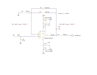
  • Hello Jerry,

      Your understanding is correct; the supply voltages are within limits of the device and this device is rail to rail output. Therefore, output voltage at 100 ohm load (assuming 50 ohm matching at output) should be within around +/- 400mV away from supply.

       I don’t see any issues with your schematic. What is your input signal frequency/characteristics (sin, pulse). Also, can you try a 0-0.5V input signal at+/-2.5V and observe the output voltage?

    Thank you,

    Sima

  • Hi Jerry,

    the LMH6611 may oscillate. Do not directly connect the scope probe or DVM to the output of OPAmp but insert a suited isolation resistor first.

    Kai

  • Hi Sima,

    The below block diagram is my circuit, 

    PD - photodiode

    TIA - LTC6268 (from ADI)

    OP - LMH6611

    The photodiode detects photon from laser diode, then output small current to TIA which will convert this small current to voltage, then TIA ouptuts to LMH6611.

    OK, I will try a 0-0.5V input for LMH6611 supplied by +/-2.5V and obsever the output voltage,actually I believe that I had done 0-0.5V input for LMH6611 before, since I increased laser diode power then photodiode will output much current.

  • Hi Sima,

    We did some of output testings by using LMH6612 instead of LMH6611, I believe the electronical character between LMH6612 and LMH6611 should be same as each other.

    The below video shows that green bar is for input and yellow bar is for ouput, we increase input of LHM6612 and hope the LMH6612 output can reach 2.0V, however the video shows when increasing LMH6612 input voltage, LMH6612 ouput is saturation at 1.7V

    green bar is for input and yellow bar is for ouput, 

    when change supply power +/-3.3V to LMH6612, increase  LMH6612 input voltage, then LMH6612 ouput is saturation at 2.7V (watch 3.3V.mpg)

    when change supply power +/-5.0V to LMH6612, increase  LMH6612 input voltage, then LMH6612 ouput is saturation at 4.3V (watch 5V.mpg)

    Another queation is as below

    you said "output voltage at 100 ohm load (assuming 50 ohm matching at output) should be within around +/- 400mV away from supply."

    Does you mean the LMH6611(LMH6612) output is related to it's load impendance?, how can I reduce +/- 400mV away from supply to +/- 100mV?

  • Hello Jerry,

      Thank you for the scope shots and detailed overview; they were very helpful!

      The LMH6611 and LMH6612 are similar, but there are some slight differences in the specs:

        Your understanding is correct. With a 150Ohm load, the voltage output range is around 300-400mV and closer to 500mV over abs max temperature ratings. This range will worsen slightly with a heavier load of 100Ohm. These devices are specified closer to the voltage rails of the device in a single-supply configuration with circuit referenced to mid-supply as shown on pages 4 and 6. Higher voltage supplies is shown to lessen the output voltage range which is what you were seeing with +/-3.3V vs +/-5V (2.7V vs 4.3V in terms of difference from power supplies). 

        For the scope shots, it looks like the voltage input/output is at a gain of 2V/V; is that correct in reference in schematic above which shows around 6V/V gain? If +/-100mV is needed for your design + split supply configuration, we can help find an alternative device. What are your bandwidth requirements based on your photodiode? 

    Thank you,
    Sima

  • Hi Sima,

    • I expected LMH6611 can ouput max voltage at 2.0V, it looks that LMH6611 limitation which can't meet my request, please introduce me alternative device which is with at least 200Mhz bandwidth, it is better for me if the device you introduce is pin to pin compatible with LMH6611, thanks for your quickly feedback.
  • Hello Jerry,

       From above spec table, the LMH6611 should still be able to obtain 2.0V if power supplies are set to +/-2.5V. As a quick test to eliminate current/load dependence, set the load resistor from scope to high impedance. Impedance matching shouldn't be a concern for a test at DC/low frequencies. 

       Otherwise, depending on your final gain/bandwidth configuration I would suggest the OPA836 or OPA356. Critical figures from OPA836:

    Thank you,
    Sima