Because of the holidays, TI E2E™ design support forum responses will be delayed from Dec. 25 through Jan. 2. Thank you for your patience.

This thread has been locked.

If you have a related question, please click the "Ask a related question" button in the top right corner. The newly created question will be automatically linked to this question.

INA1620: Matched resistor usage and CMRR, PSRR

Part Number: INA1620
Other Parts Discussed in Thread: OPA1637

After receiving a positive indication regarding being able to use a digital potentiometer in an INA1620 application to set gains in the forum thread "INA1620: Recommendation for Multiple Fixed Gain Settings", I would like to ask another question about the use of the matched resistors in the part.   

Because of assembly costs, reducing the number of components is critical.  The Mic Pre I am developing, and asked about will provide me the gains necessary for a microphone, and a low level line input with excellent PSRR and CMRR numbers.  However, I now have the requirement to handle up to +16dBu on this same audio channel, which obviously needs to be attenuated so it won't saturate the AD converter.   

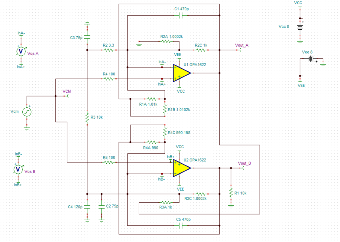
From the original TINA circuit provided, I implemented the two unused pairs of matched resistors, placing them in parallel with the feedback resistor to give me negative gain.  Simulation showed it doing what I want, but I cannot see any TINA simulation of CMRR or PSRR when doing this.  Is there a CMRR, PSRR simulation in TINA?   Would using the matched resistors in this way adversely affect the CMRR and PSRR numbers?  I understand this will not drop the level to where I need it to be, but it gets me closer in this one block. 

I have attached the updated TINA design for your review.

  robert_ina1620_RS2.TSC

Thank you again for your help and guidance.

  • Hello Robert, 

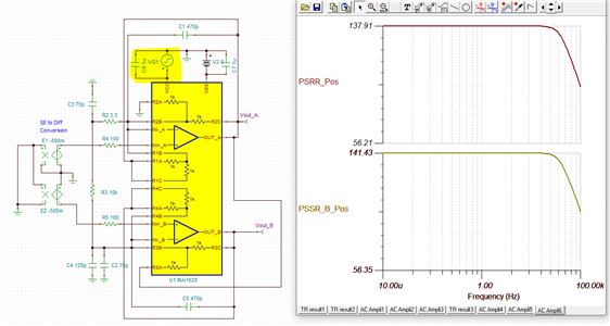
    I injected a disturbance signal on the power supply as shown below and checked the frequency response. The AC signal generator VG1 shown below has an 8V DC value such that it keeps the device biased from a DC perspective. 

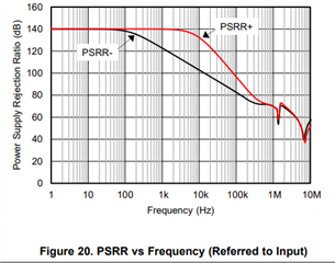
    You can see that the PSRR matches well with the specification in the product data sheet which is 0.1 uV/V or 140 dB. This also closely aligns with the product datasheet curve for PSRR. 

    In general the CMRR performance due to component values will largely be dominated by the external component matching in the differential path. This is because the discrete component tolerances would likely be greater than that of the on die resistor matching. I will take a look at simulating this as well and respond here. In the mean time if  you have further questions feel free to reach out. 

    Best Regards, 

    Chris Featherstone

  • Thanks, Chris.  If using the different sets of matched resistors in the way proposed will not maintain the CMRR and PSRR the way I need for the mic levels, would you see an alternative way of being able to drop that +16dBu down by 12db?   Thanks again.

  • Robert, 

    We are currently discussing this and will respond within two business days. Thank you for your patience. 

    Best Regards, 

  • Not a problem, thanks for your expertise on this...

  • Hey Robert,

    I'm going to jump in here as well - what is the ADC you are driving?  I assume you are looking for a fully-differential output?  This may not be the easiest way to accomplish a fully-differential output stage, I can understand the value of the matched resistors but ideally you would have a symmetrical output stage to achieve proper fully-differential signals, as in an FDA like OPA1637.

    Regards,
    Mike

  • Thanks, Mike, the more the merrier!  We are driving an AD ADAU1772 (Sorry TI) which has 4 single ended audio inputs, so I don't need the differential output for this design.   When I saw the INA1620, I was focused on the CMRR and PSRR + EMI Filtering it provided.  Now if I can just get it to provide the wide range of gains I need, without another stage, I'll be golden...   This design has eight channels, and with the cost of assembly these days, I need to keep the component count down, way down...

  • Hello Robert, 

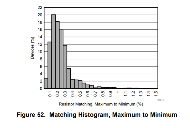
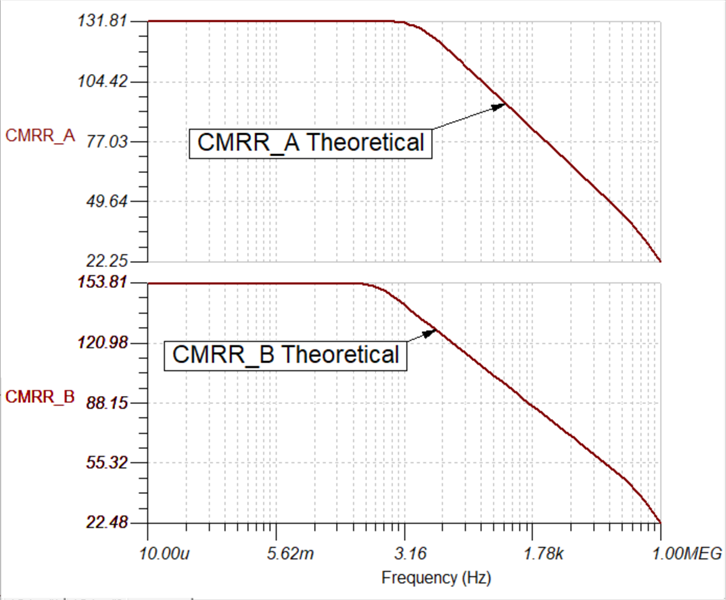
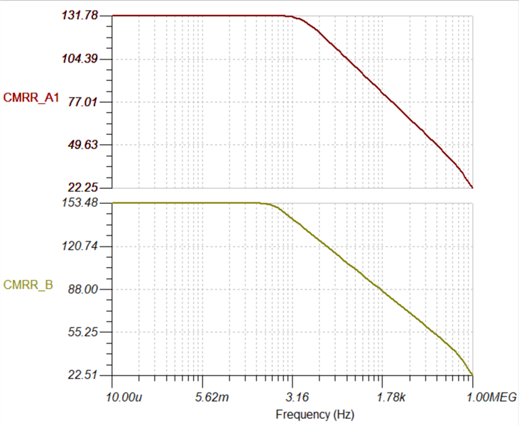
    I built a discrete INA1620 in the 3 op amp INA configuration. I did a cursory check where I assumed the matched pairs are our worst case matching in the PDS of 0.02% for resistors in the same pair. I also took an extreme case from the distribution shown below of 1% mismatching between matched pairs. From there I checked the CMRR against the theoretically perfect set of all resistors and found the CMRR difference in simulation as shown in the plot below. 

    Mismatched as described above I see a very small change on both amps. 

    The PSRR should not be impacted by these components as they are not in the power supply path. 

    Here are both of the simulations. A sensitivity analysis can be performed with these resistors by adjusting the resistor tolerances. Based on the results above I don't see a huge concern. Let me know what you think. I hope this is helpful for your analysis. Below is a link on how to perform the CMRR and PSRR analysis. I believe if you run my sims the CMRR results should show up since I included the post processing equations within the files. 

    Let us know if we can be of further assistance. 

    INA1620 CMRR Sim Mismatch.TSCINA1620 CMRR Sim Theory.TSCDiscrete INA1620 CMRR Mismatch.TSC

  • Sorry for the late reply getting back to you, but I really thank you for researching this with the detail you did.  Based on your data, yes, it seems I should be able to do what I proposed without too much negative effect.  I will look further into your model and if I have any further questions, I will post another question.  Thanks again!