This thread has been locked.

If you have a related question, please click the "Ask a related question" button in the top right corner. The newly created question will be automatically linked to this question.

OPA3S328: Internal Switch usage

Part Number: OPA3S328
Other Parts Discussed in Thread: OPA2328,

Hello,

I currently have an OPA2328 designed into a circuit, and I have a need for two very low leakage analog switches.

Being that the OPA3S328 is essentially a OPA2328 with analog switches built it, I'm very interested in using those low-leakage switches.

Other than being conscientious of not disabling the amplifier based on switch-inputs, is there any problem with using the analog switches in the OPA3S328 for functions unrelated to the amplifier itself?  I assume that they are not intertwined in any way?

Thank You,

Ben

  • HI Ben,

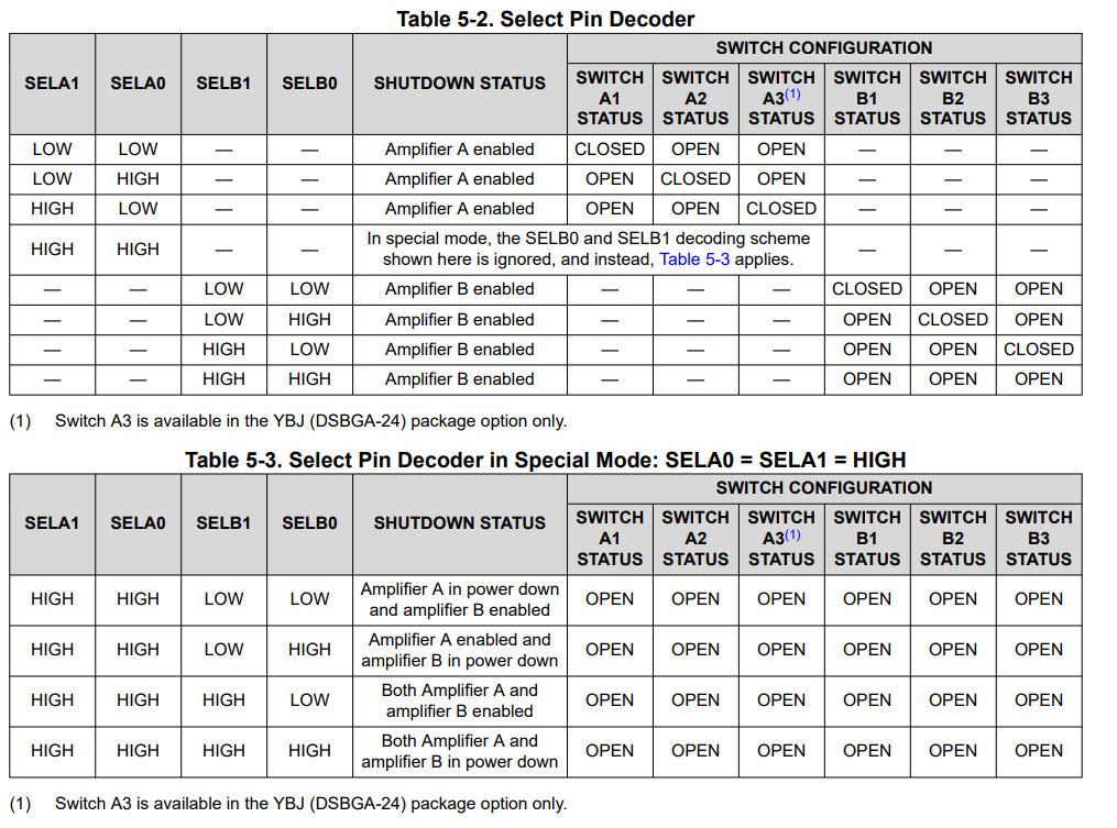
    From the switch control point of view, as you have correctly mentioned, the user has to ensure to set SELA1, SELA0 and SELB1, SELB0 ensuring the amplifiers are enabled as shown on table 5-2.  Table 5-3 shows the special mode SELA0 = SELA1 = High, where one or both of the amplifiers can be set to power down.

    Please note, the OPA3S328 switches exhibit the make-before-break switching behavior, meaning when programmed to a different position, the previous switch does not change to high-impedance (open) state until the other switch closes with a typical 2-µs delay when both switches are closed. Since these switches are intended to change the feedback components on the amplifiers, this feature keeps the amplifiers from operating in an open-loop state when the switches are used in a switched-gain transimpedance configuration.

    This is different to standard multiplexers that feature the opposite break-before-make switching behavior, since on the standard multiplexer application, the user wants to avoid shorting two different channels.

    Thank you and Kind Regards,

    Luis