This thread has been locked.

If you have a related question, please click the "Ask a related question" button in the top right corner. The newly created question will be automatically linked to this question.

LMP7704: 10uA Current Source Design

Part Number: LMP7704

Greetings,


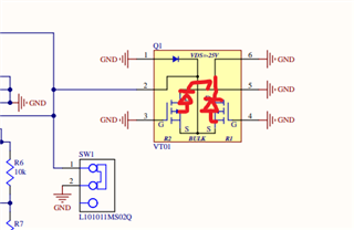
Attached is a schematic for a radiation sensing circuit. The circuit uses the LMP7704 as a 10uA current source. The design was created using the current source reference circuit in the LMP7704 datasheet. The 10uA source is fed to the radiation sensor per the rad sensor design specs. The rad sensor is a varadis RADFET VT01. There is some resistance across the RADFET which will create a voltage. That voltage is fed into a unity gain buffer to isolate the 10uA current source from the resistor divider.

With that being said the circuit does not work as expected. To test just the current source, I removed the RADFET and placed a 200k resistor between the VCCS net and ground. I would expect the VCCS net to be 2V if the circuit were working properly (200k ohm * 10uA). During this I also left the switch in the open position as to not short VCCS to ground.

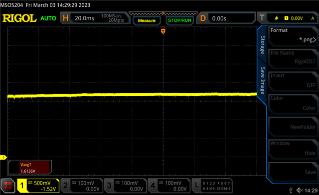
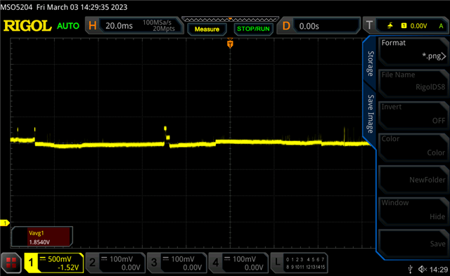
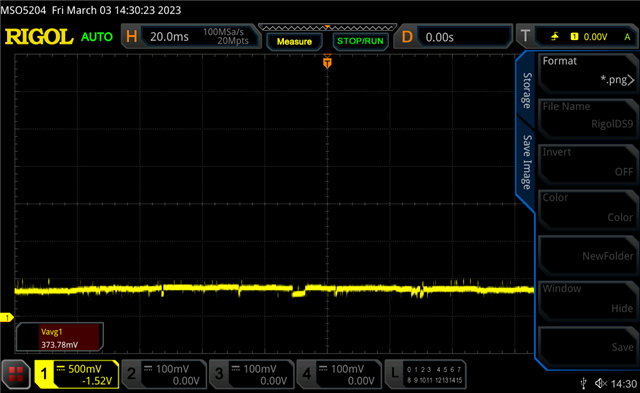
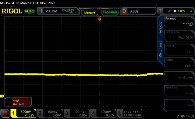
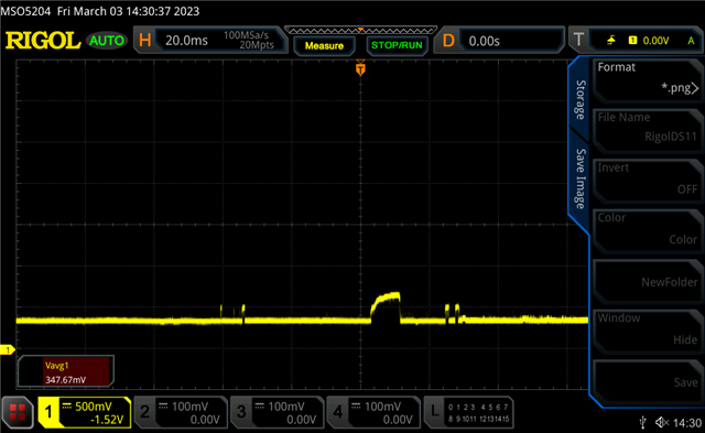
I've also attached oscilloscope captures of VCCS. Is there anything you can comment on in regards to the current source design?


Thank you,


Derrick

https://netorg166142-my.sharepoint.com/:f:/g/personal/andreassi_sensornetworksinc_com/EpCu0l0_419Puv6PB-hPzH4BIV0R5VZlSHNv6BRvrG5HDA?e=ZMpOcg

PS. Please let me know if this link does not work. Not sure of the cleanest way to add pictures.

  • Hello Derrick, 

    We are currently looking into this and will respond within 2 business days. 

    Best Regards, 

    Chris Featherstone

  • Hi Derrick,

    It took me a minute to understand how you have this connected but I see now this is an "Improved Howland Current Pump" architecture, as seen in the app. note below.

    https://www.ti.com/lit/an/sboa437a/sboa437a.pdf

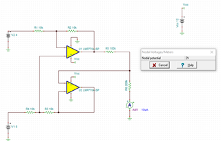
    Fundamentally it should work - I tested the general connection in a TINA sim:

    The biggest question I have is why is Q1 necessary - the MOSFETs will have a body diode from S to D, meaning that the voltage could never really go 1 diode above ground.  Have you tried to measure it after disconnecting Q1?

    Regards,
    Mike

  • I've attached the VT01 datasheet. Pin 2 of Q1 must be connected to ground at all times while under irradiation. This is the reason for the switch to ground. Then, when we decide to read the radiation readout from q1, we must force 10uA into pin 2.

    However, for this forum, I removed q1 and placed a 200kOhm resistor between the VCCS net (pin 2 of q1) and ground. My assumption would be that we are forcing 10uA through a 200k resistor which will result in 2V. However that is not the case and I am getting various voltages and a lot of rail to rail noise.

    VT01-Datasheet.pdf

  • Ok.  I do see all of the scope shots with the noise - are they all taken at the VCCS node?

    Can you measure the voltages at the output of the amplifiers A and B (pins 1 and 7)?  This would be very helpful to see what may be going on.

    Unrelated (I believe) note: we don't recommend to short the inputs of the amplifier on amp D, this will certainly drive the output into either the positive or negative rail.  The ideal way to configure an amp. that is not used would be to connect it as a buffer (output to inverting terminal) and terminate the positive input at a voltage between the rails.  The general reason to not force the amplifier output to the rail is because on many devices this can increase Iq, I'm not sure if this is the case with this device but it still would be best to avoid the output in the rail.

    Regards,
    Mike

  • Thanks for the info Mike. Yes, all scope captures were taken from VCCS node.

    Here's the captures of the outputs.

    Pin1 

    Pin 7

  • Hi Derrick,

    These voltages seem to vary by hundreds of mV, and it doesn't look like an instability, so I don't believe it is related to the actual design itself.  It seems like there is either a bad connection somewhere, or, the device has somehow failed.

    Are you able to measure the quiescent current of the amp?  This would be a good indicator if there is some problem with the amp.  

    On that note, the abs. max. for this part is 13.2 V.  You are running it right at 12 V, which is Ok, but does get close to the abs. max.  What is the power source for this board?  Is it possible that there is a cable connecting the power, and the cable is ringing?

    Regards,
    Mike