This thread has been locked.

If you have a related question, please click the "Ask a related question" button in the top right corner. The newly created question will be automatically linked to this question.

OPA455: OPA455 Output current to be increased

Part Number: OPA455
Other Parts Discussed in Thread: LM1875, LM2876, TINA-TI

Hi texas team,

    I am using OPA455 to generate +/-120vpp sine wave signal(Supply Voltage +/_ 60V) but as per my requirement i need to drive 500mA load. Kindly suggest how to increase output current.

Thanks 

Saravanakumar D 

  • Hi Saravanakumar,

    I am using OPA455 to generate +/-120vpp sine wave signal(Supply Voltage +/_ 60V) but as per my requirement i need to drive 500mA load.

    You would need to increase the supply voltage rails above ±60Vdc, likely  ±65Vdc to ±70Vdc range due to the head room of the op amp. 

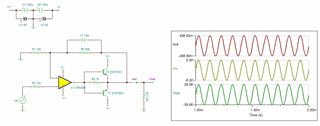
    Without knowing the design requirements, here is a simple example. 

    OPA455 120Vpp 03032023.TSC

    You would need to add current booster stage with AB class complementary stages (BJT or MOSFET drivers). You need to resolve the cross over distortion issues, and will require to have current limiting feature to protect the output drivers etc.. 

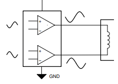
    If the load can be driven in a floating manner, you may implement push pull method to double the output voltage swing. Just see Kai's response, maybe this is what he has in mind. 


    Best,

    Raymond

  • Hey Raymond,

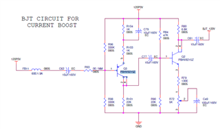
    Your suggestion are as per my need, Thanks a lot. Kindly help me to clarify, is there any issue by adding below circuit for current booster stage. Suggest me any hi current MOSFET driver for this application. 


    Thanks 

    Saravanakumar 

  • Kindly help me to clarify, is there any issue by adding below circuit for current booster stage.

    Have you already run a simulation with this circuit? What are your results? Please post your simulation file.

    Kai

  • Hi saravan, 

    Have you simulated the above circuit as current booster? What is the 120Vpp driving application?

    You have to deal with the same issues about the crossover distortion, output voltage swing limit, phase distortion etc.. You would have less issues in dealing with differential drive that Kai simulated for you (if you are able to use it.). These are proven solution, and will not take much PCB real estate. 

    You can search for HV and HI mosfets for audio application over the internet. You may search for International rectifier website (infineon.com) website and try to find complementary mosfets for the application.

    If you have additional questions, please let us know. 

    Best,

    Raymond

  • Hi Raymond,

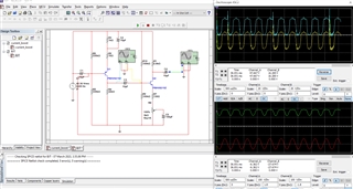
    Simulation results are not proper. kindly take a look.

    Regards

    Saravanakumar D

  • Hi Hi saravan, 

    Please provide us with the Tina simulation file, and I will take a look at the circuit. Please keep in mind, E2E is a platform that are used to support TI products. 

    There are many buffer output stages that will work with amplifier feedback circuit, but none of them are perfect (have pros and cons in certain application). You need to tell us what is the type of driving application and we may be able to provide you with better recommendation. 

    Best,

    Raymond

  • Hey Raymond,

    I understood, We are going to use this circuit to drive LVDT application. Its supply requirement is 36Vrms 0.5A.

    Thanks

    Saravanakumar D

  • Hi saravan, 

    Since the driving application is for LVDT, I would recommend to use the driving topology that Kai simulated. 

    There are number of reasons:

    1. The transformer has to be drive in AC signals; the driving signals have to eliminate DC offset voltages or minimize the differential DC voltage offset across the transformer terminals (concerns about the magnetic saturation of a transformer).  

    2. The push pull topology can double the output voltage swing for a floating load or transformer, thus even 2X - 60V power amp drivers can deliver up to 36Vrms (102Vpp), 0.5Apk voltage swings. This is advantage of differential driving architecture, also the topology will have higher CMRR for the application. For instance, LM1875 ($1.583/1ku from TI e-store) is a great audio power amplifier (20W, high stability, low distortion, current limiting, reduced noise, increased linearity, thermal protection advantages etc.), which it should work well with the driving application. 

    https://www.ti.com/lit/ds/symlink/lm1875.pdf?ts=1678282569912&ref_url=https%253A%252F%252Fwww.ti.com%252Fproduct%252FLM1875

    3. Since these power amplifiers are designed for audio application, they have very low THD, which are great driver for the application and keep accurate drive for the sensing application. In addition, your application is likely operated between 1kHz -20kHz range (may go up to 50kHz for a typical laminated Si steel stamping transformer).

    Anyway, there are many advantages over the discrete output driving architecture, where a designer has to implement many of the integrated features into a circuit, and it may cost more and has poorer performance or results. 

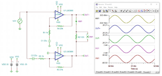
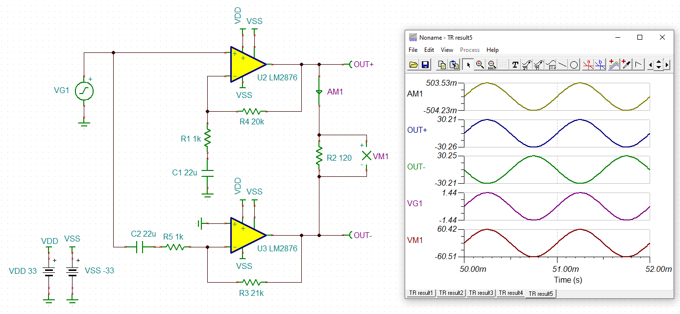
    I did a quick simulation per your application, and hope this helps. As you can see that the output Vdiff is matching and common mode voltage is excellent. The output driver is directly coupling to the transformer. You may also try capacitive coupling as well.  

    LM1875 36Vrms 0p5A Driver 03082023.TSC

    If you additional questions, please let us know. 

    Best,

    Raymond

  • Hi saravan, 

    I hope that the simulation is helpful for your project. 

    I am going to close this inquiry. If you have additional questions, please let us know. 

    Best,

    Raymond

  • Hi Raymon,

    Thanks for your support, I hope if I replace the op-amp from LM1875 to LM2876 it should deliver the same output.  

    Saravan

  • Hi,

    why not running a TINA-TI simulation? TINA-TI is super easy to handle and is free:

    https://www.ti.com/tool/TINA-TI

    Kai

  • Hi Saravan,

    I replace the op-amp from LM1875 to LM2876 it should deliver the same output.

    Kai's recommendation will work. As Kai pointed out, you should simulate the circuit before putting it together. Since the circuit is driving a transformer, many unexpected transient events may occur and you need to place certain protection circuitry and find solutions to counter the unexpected system behaviors.  

    Best,

    Raymond