Other Parts Discussed in Thread: TINA-TI
Hi, I'm not able to get the correct resistor values based on my understanding of the parameters of this device.
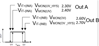
My requirements: TLV6710 configured as Window comparator with OutA and B tied together OutA/B "0" when Vmon between 0V and 2.4V. When Vmon rises above 2.4V, OutA/B is "1". When Vmon goes above 2.7V, OutA/B becomes "0". When Vmon drops to 2.6V and below, OutA/B is "1". See diagram pasted below.
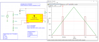
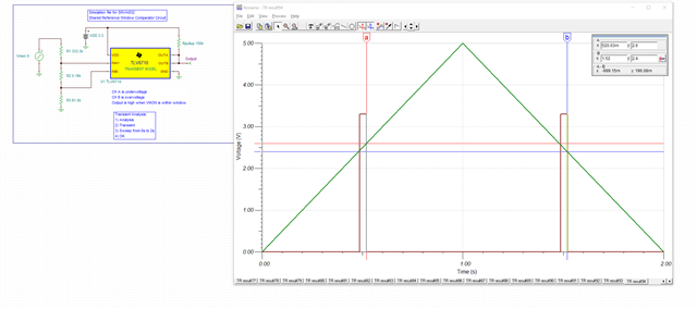
I ran the TINA-TI simulation on your website and got the R values experimentally, but I can't reconcile with my calculations. Much of the confusion is the definition of, and the relationship between these variables:
VIT+(INA), VMON(UV_HYS), VIT-(INA), VMON(UV), VIT+(INB), VMON(OV), VIT-(INB),VMON(OV _HYS).
I think the relationship is the following from the datasheet:
VIT+(INA) = VMON(UV_HYS), VIT-(INA) = VMON(UV), VIT+(INB) = VMON(OV), VIT-(INB) = VMON(OV _HYS). This is from 9.1.1 ("The highest accuracy threshold voltages are VIT–(INA) and VIT+(INB), and correspond with the falling undervoltage flag, and the rising overvoltage flag, respectively."). The sticking point are the words "correspond with". Please correct me if I'm wrong.

Also, the example in the datasheet is confusing, specifically why VIT+(INB) and VIT-(INA) are 0.4V (I see nothing in the example requirements that point to 0.4V and I can't figure out how to derive it).
This 0.4V seems to be contradictory to multiple places in the datasheet that indicate that these values should be in the window range VIT+(INB) around 26.4V and VIT-(INA) should be near 21.6V (for example, section 6 says when INB exceeds VIT+(INB), OUTB is driven low).
Please help me sort this out, preferably showing the calculations with my requirements.
Here's a screenshot of my simulation. I don't think it exactly lines up with my requirements, but it is close. Much closer than what the calculations give me.


