This thread has been locked.

If you have a related question, please click the "Ask a related question" button in the top right corner. The newly created question will be automatically linked to this question.

THS3491: THS3491 feedback resisor selection

Part Number: THS3491

Hi, Support

     In the datasheet of the amplifer, it only mentioned the gain resistor value selections on Rg and Rf. 

Is there a requirement on the resistor package? how can we calculate the power requirement on these resistors??

also, why the RGT ad DDA package part have different Rg, Rf resistor value??

thanks

Li

  • Hi Li,

    have you seen the "Bill of Materials" in the "EVM Users's Guide"? -> "0603" packages are used for the feedback resistors. Eventually "0805" can also be used. In any case, these resistors must be suited for HF-applications.

    The resistors must withstand the power U^2 / R where U is the signal voltage dropping across the resistor. What signals are you using? Can you show a schematic?

    RGT and DDA packages need different optimized feedback resistor values because they bring along different parasitic circuit elements (bond wire inductances, stray capacitances, etc.)

    Kai

  • Hi, Kai

           yes, I saw the BOM of the EVM board, but not very sure how the power get calculated.  And we are using RGT package.

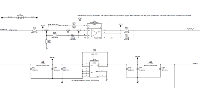
    please see attached for the schema.  the input signal is at +/-1.5V and the output is at +/-10V.  the gain is about x6.6.

    the Rf is 750Ohm.  based on what you said,  the P = (10-1.5)2/750 = 0.1W

    the Rg is 133Ohm, then P = 1.5*1.5 / 133 = 0.017W

    Is this correct?

    thanks

    Li

  • Hello Li,

      Yes, that is correct. Though, I do recommend keeping the feedback resistor to a similar value (around 500-550) as suggested in the datasheet. Then, adjusting the RG value based on your exact gain requirements.

       Overall, there is a tradeoff to both adjusting the feedback resistor value. Decreasing the feedback resistor will result in increased power dissipation from the amplifier since the overall load seen at the output of the device will be reduced. Increasing the feedback resistor, will lower your bandwidth and may have an effect on stability. 

    Thank you,
    Sima 

  • Well Table 9.2 gives you some guidance, 

    For a gain of 6.6 using the RGT, perhaps an Rg = 100ohm and Rf = 562 would be closer, 

    Also, this lower circuit is completely wrong, hope you are not doing this, 

  • Thank you, Michael.  Can you please help explain why you say the circuit completely wrong?  I think there the cap C423 shouldn't be there.  is this one you mean?

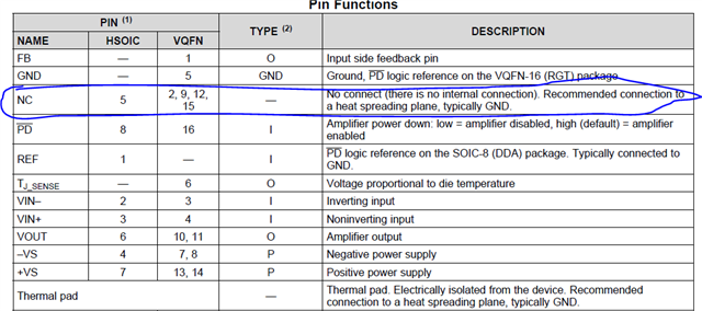
    For NC pins, in datasheet,  its says no internal connections and recommended to connect to GND.

    thanks

    Li

  • Oh I see now, you just had a seperate drawing for the power supply and other things, no that is fine, 

  • thanks Michael!