This thread has been locked.

If you have a related question, please click the "Ask a related question" button in the top right corner. The newly created question will be automatically linked to this question.

INA333: INA333

Part Number: INA333

Hi TI,

I'm unable to drive INA333 from USB-6001 (NI DAQ) using Analog Output pin. Please see below Spec of USB-6001.

Please see below logic used to drive INA333 with Gain = 455, VSW - 2.8V.
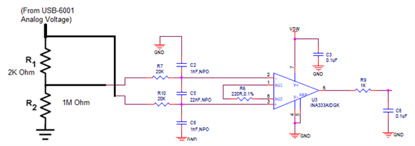
I've used even below bridge configuration also but did not get desired output.
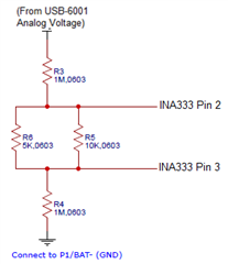
Please see below table of input voltages and corresponding voltage measured.

Vin (V) 0 2.0021 1.3324
Volt @ J2.2 (V) - INA333 Pin 2 0.00301 2.0021 1.3324
Volt @ J2.3 (V) - INA333 Pin 3 0.00464 1.9977 1.3288
Calc Diff (V) 0.00163 0.0044 0.0036
Calc Inst Amp O/P (V) 0.74165 2.002 1.638
Measured Inst Amp O/P (V) 0.9648 1.576 1.353522

  • Hi Girish,

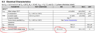
    in the case where you are applying 0V input signal, you are violating the input common-mode voltage range of the INA333. The minimum input voltage is V- + 0.1V, which for your power supplies is 100mV.

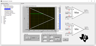
    In addition to the input common-mode range of the INA333, there are additional common-mode and voltage swing limitations due to the INA architecture that are internal to the device. In order to simplify the linear behavior analysis of INAs, we generate boundary plots for our integrated INAs that you can use to determine valid output voltages depending on the common-mode input voltage, differential input voltage, gain, and power supply voltages.

    As you can see from the boundary plot below, for your circuit, with a common-mode input of 2V, the maximum output is 1.5V, which is consistent with your measurement.

    This tool is available at the following link: Analog Engineer's Calculator

    Once you download the Analog Engineer's Calculator, open the tool and select "Amplifiers and Comparators" --> "INA Vcm vs Vout". From here you may select your INA device, your power supplies, and your gain. Then you may generate the Vcm vs Vout boundary plot you see above.

    This TI precision labs video: https://www.ti.com/video/series/instrumentation-amplifiers.html goes into great detail about this topic if you are interested.

    Regards,

    Zach

  • Hi Zach,

    Thank you for the reply.

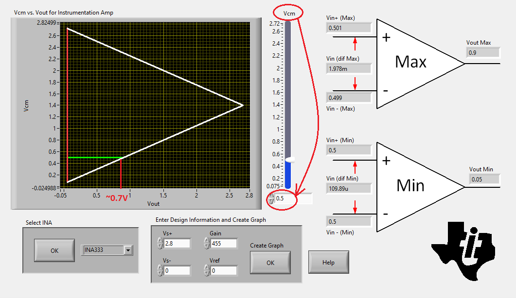
    Even when I provide an input voltage (Vcm) of 0.5V, I'm reading constant 0.7V at the output.

    Vin - 0.5V, Vout - 0.705V

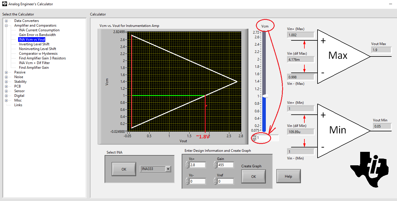
    Vin - 1V, Vout - 0.705V

  • Hi Girish,

    Vout of ~0.7V for Vcm of 0.5V and Vin_diff=0 is the correct Vout limitation - see below.

    For Vcm=1V and Vin_diff=0 the Vout=~1.8V (see below).  Since Vout=Vref+Vin_diff*Gain, Vout=0.7V would require Vin_diff<0.