This thread has been locked.

If you have a related question, please click the "Ask a related question" button in the top right corner. The newly created question will be automatically linked to this question.

THS4521: Schematic check

Part Number: THS4521
Other Parts Discussed in Thread: ADS1178, , THS4551

Hi TI Tech Team

I have an application interfacing a THS4521 to an ADS1178 16 Bit differential ADC. Vref of the ADC is 2.5V. Maximum input signal can be up to +/-15V sinusoidial,

which is why Ive opted to use the attenuation circuit suggested in SLYT341. Is there anything obviously wrong with my circuit? simulations seem OK to me, with 

the input to the ADC being +/-2V (4V p-p). Any suggestions would be appreciated, ive provided Tina Simulations and a schematic below. Thanks in advance
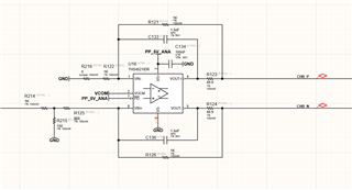
THS4521_SE_to_DIFF_Thevenin.TSC

  • Hello Arif,

    I will do a schematic review for you; please expect an update by the end of the week.

    Best,

    Alec

  • Hello Arif,

    I have some follow-up questions:

    1. What is the desired gain or attenuation for your circuit?

    2. You are converting a single-ended input into a differential output into for the ADS1178, correct?

    3. Are your concerns regarding whether the circuit correctly does what you intend to do (if so, please elaborate on what you are doing with the circuit)?

    4. Or are you looking for feedback on items you may not have thought of?

    I am calculating a gain of 17 from my interpretation of the document on attenuation you mentioned above; perhaps I am missing a piece of context.

    Best,

    Alec

  • Also Arif, the THS4521 is quite old, the THS4551 was done as a drop in update and improved on many features (noise, DC precision, HD)

  • Hi Alec

    Thank you for your response. Answers to your questions

    1) My input signal (input of R214) is +/-24V. I am trying to attenuate down to 4V. The THS4521 will have a gain of 1

    2) Yes my input signal is single ended bipolar, which is being converted to differential for the ADS1178

    3) My concern is that Im not sure the circuit is attenuating the signal properly to feed the ADS1178 +/-24V in, 4V out from THS4521

    4) If you have any feedback on items Ive overlooked (CM range of input or output of the THS4521, offset issues)

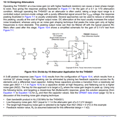
    My understanding of SLYT341 is that, looking back from Vin(+), the impedance is R214//R215 + R125 = 1k//150 + 866 

    This makes Rin approximately 1K, and therefore the gain would be R121/Rin = 1k/1k = 1. Maybe I am missing something here?

    Also, I didnt realise that there was a THS4551, thank you for the suggestion, at least now I have 2 devices I can use in the BOM.

  • Well Arif, this requirement comes up a lot, hence I put this section into the THS4551 datasheet, 

  • Michael

    Brilliant, thank you so much for your help and patience. I believe this will get me to the right solution.