This thread has been locked.

If you have a related question, please click the "Ask a related question" button in the top right corner. The newly created question will be automatically linked to this question.

INA129-EP: Vout shorted to RG pin 8

Part Number: INA129-EP
Other Parts Discussed in Thread: INA129

I am currently working on a failure modes effects and criticality analysis and was wondering if you can give me some insight into how an INA129MDREP instrumentation amplifier will behave if the output is shorted to RG pin 8? Pins 1 and 8 are open for a gain of 1 and the supply voltage is +/-12v. Inverting input is GND and the non-inverting input is 2.5V.

Thanks in advance.

  • Hi Robert,

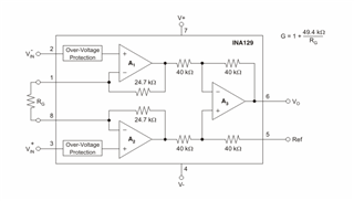
    From the INA129 internal block diagram and your circuit description, you are shorting the output of gain stage A3 to the inverting input of gain stage A2.

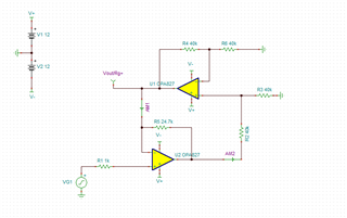
    For simplification, let us assume the output of gain stage A1 perfectly follows the input at Vin- (0V) and the resulting circuit can be simplified to the circuit shown below.

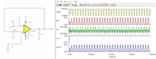
    In this case, both amplifiers are attempting to drive the Vout/Rg+ node. The A3 stage is driving the node directly, while the A2 stage is driving the node through the 24.7kΩ feedback resistor and the A3 amplifier. This will result in unstable operation and the device will oscillate as shown in simulation of the INA129 step response with the output shorted to pin 8.

    The main concern from a failure perspective, is the high amount of current that can be driven into the inverting input of the A2 amplifier stage which can cause damage to the device.

    Regards,

    Zach

  • Hi Zach

    Thanks for the helpful information. I just have one last question. If the device is damaged from the high amount of current driven into the inverting input of the A2 amplifier stage how would that effect the output after the damage occurs? Would the output be driven to one of the supply rails or would there simply be no output at all. 

    Thanks again,

    Robert

  • Robert,

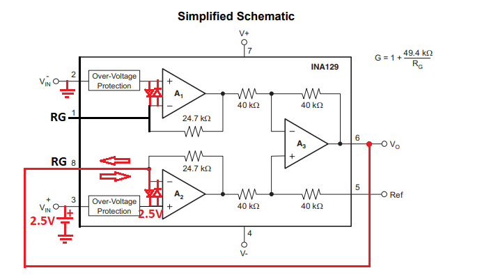
    Under normal operation pin 1 is at virtual short with pin 2 and pin 8 is at virtual short with pin 3 and nothing other than RG resistor should be connected to pin 1 and 8.  This means that under conditions you describe pin 8 is internally driven to 2.5V while pin 1 is at 0V.  Thus, depending on the REF voltage shorting the output to pin 8 may result in a high current through back-to-back input protection diodes shown in the diagram below.  If this current is greater than 10mA, these diodes may be damaged shorting pin 8 and 3 and allowing the current flow between them - this would result in the circuit stop operating all together with the output being driven to one of its rails (12V or -12V).