This thread has been locked.

If you have a related question, please click the "Ask a related question" button in the top right corner. The newly created question will be automatically linked to this question.

Amplification of cardiac signal.

Other Parts Discussed in Thread: TINA-TI, OPA344, TL082, TL072, TSV911, TL072H

Greetings everyone!

I am John Mark Ludovice, an Agricultural and Biosystems Engineering student from the Philippines, currently working on my undergraduate research. I am trying to develop a handheld automated egg candler using the principles of photoplethysmography. However, I have difficulties making my amplification and filtration circuit work.

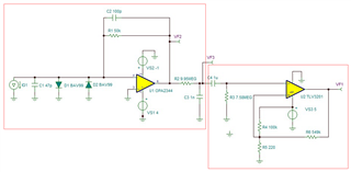
I am trying to amplify the cardiac signal using an OPA344 amplifier with a cut-off frequency of 16 Hz. Then I applied a passive RC high-pass filter with a cut-off frequency of 23 mHz. Then I incorporated a comparator to detect the peaks. I simulated it using TINA-TI and here are the results:
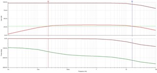
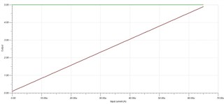
However, whenever I try to create a prototype, the system is very erratic. I've tried putting a probe on the output pin of the OPA344 and the signal is not as expected. I have little to no knowledge with regards to electronics hence I badly need some help.

Thank you!

  • Hi John,

    I would try to optimize the circuit in the following way:

    1. Choose a feedback resistor that is small enough so that the output of OPAmp never clips, even not with ambient light of high intensity. Because when the output of OPAmp clips the photodiode becomes reverse biased and can damage the OPAmp. In any case you leave the common mode input voltage range and the OPAmp can behave very weird.

    -> Whatever you do, the OPAmp must never clip!

    I would mount two antiparallel BVA99 in parallel to the photodiode as discussed in this thread:

    https://e2e.ti.com/support/amplifiers-group/amplifiers/f/amplifiers-forum/1195704/opa356-current-or-voltage-limiter-for-tia-to-in-

    I would even think about running the OPAmp with a bipolar supply voltage. +4V and -1V would be a good idea. Then you would no longer need the pseudo ground generation (R2, R3 and C3) but can connect the +input of OPAmp directly to signal ground. And clipping the output of OPAmp due to ambient light of high intensitiy would no longer be a problem either.

    2. The feedback capacitor is too big and destabilizes the OPAmp. Take something between 22pF and 100pF instead of 134.7nF. If you want to low pass filter the signal, then don't do it in the feedback loop of OPAmp but do it later in the signal chain.

    3. Never directly touch any pin of OPAmp with the scope probe or multimeter but always insert an isolation resistor first. This is discused in the datasheet. See figure 5. I would recommend to use a 100...220R isolation resistor.

    4. There's a good chance that the OPAmp became already damaged during the experimenting. So, best you take a fresh OPA344 and check again.

    5. Before you run the circuit with a single supply, you may want to start your experiments with a bipolar supply voltage first. This will heavily simplify the circuit. I would recommend to make the circuit first work with a TL082 (or similar) and two 9V batteries (+/-9V) and make it work with a single supply voltage and the OPA344 in a second step.

    Divide and conquer ! 

    Kai

  • Greetings, Kai!

    Your suggestions are highly appreciated. However, I have further clarifications to make.

    I am using a Vishay BPV23NF photodiode to capture the cardiac signal. Do you think the feedback resistance that I use is already enough to amplify the signal properly? As per the photodiode's datasheet, its short circuit current is 65 microAmp, which I used as a reference for the design.

    Also, in item no. 3, you mentioned that I should filter the signal in the later stages of the circuit. Do you mean that I have to make the circuit like this Transimpedance Amplification > LP FIltration > HP Filtration > Comparator ?

    Thank you!

  • Hi John,

    I am using a Vishay BPV23NF photodiode to capture the cardiac signal. Do you think the feedback resistance that I use is already enough to amplify the signal properly? As per the photodiode's datasheet, its short circuit current is 65 microAmp, which I used as a reference for the design.

    65µA belongs to an irradiance of only 1mW/cm^2. So, higher output currents may be possible.

    I would take the naked TIA, make the corrections I suggested and connect a multimeter to the output. At the beginning keep the photodiode shielded from ambient light. Then slowely and carefully remove the shield and measure the output voltage of TIA. This gives you an idea about the proper feedback resistance. 

    Do you mean that I have to make the circuit like this Transimpedance Amplification > LP FIltration > HP Filtration > Comparator ?

    Yes, sounds reasonable. But focus on the TIA + low pass filter first. Solve the high pass filter and comparator sections in a later step. Otherwise, when wanting to solve all problems at the same time, you may run into confusion.

    Divide and conquer!

    Kai

  • Greetings, Kai!

    Does it mean I have to undergo trial and error with regard to the optimal value of my feedback resistance? Moreover, is this circuit the same as the one you recommended to me? Kindly disregard the values as those are yet to be determined. My primary concern at the moment is the connections.

    I apologize if I seem kinda slow. I have a weak foundation in electronics hence the difficulties in incorporating your suggestions into the circuit.

    Your responses are deeply appreciated.

    Kind regards,

    JM

  • Hi John,

    Welcome to E2E! :) 

    If you have not seen this reference design yet, we have one for the photodiode amplifier circuit to help design this part of the circuit: https://www.ti.com/lit/pdf/SBOA220A 

    This gives some more information on the feedback values that Kai was mentioning and can alternatively be calculated this way. 

    I would also recommend isolating the simulations to ensure the op amp with filtering is stable before incorporating the comparator segment. 
    We have a TI Precision Labs video on stability simulation here

    Please let me know if you have further questions.
    Thank you!

    Best Regards,
    Ashley

  • Hi John,

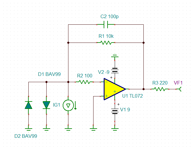
    I would start with this circuit:

    Does it mean I have to undergo trial and error with regard to the optimal value of my feedback resistance?

    Yes, of course. Unless you know the maximum light intensity of your application by theory, you have to find a proper feedback resistor by experiment Relaxed

    "IG1" stands for your photodiode. The BAV99 in combination with R2 protect the OPAmp during power downs. C2 is necessary for stability. The 10k feedback resistor sets the gain of your circuit and is probably too small but can easily be increased depending on your needs. And R3 isolates the output of OPAmp from capacitive loads like the scope or digital voltmeter and gurantees stability.

    The TL072 is rather stable in this configuration and works well with two 9V batteries.

    The low pass and high filter section we will discuss later, once you have found a proper feedback resistor R1 Relaxed

    Kai

  • Greetings, Kai! 

    Your help is deeply appreciated. However, I've been trying to source out some TL072H op-amp but it seems like it's not available locally hence I would have to buy it from international shops and wait for a week before it arrives. Do you think I can still carry out this configuration using OPA344 while I wait for the TL072H? The op-amps that I have at the moment are OPA344, TSV911, and MAX4400.

    Thank you!

    Kind regards,

    JM

  • Hi John,

    I did not mean the TL072H but the good old TL072CP. Even the TL071CP or TL074CN would do. The TL082CP, TL081CP or TL074CN would also do. At least one of them should be available where you live.

    To work with two 9V batteries it's important that the OPAmp withstands a supply voltage of at least +/-10V (or 20V).

    Kai

  • Greetings, Kai! 

    I was able to source some TL072CP op-amps. I will execute this circuit tonight and I'll provide updates on how it will behave. I will also try using different feedback resistances.

    Thank you!

    Kind regards,

    John

  • Greetings, Kai!

    I hope you're doing well. I've tried executing the circuit but I'm getting erratic signals. What do you think could've possibly gone wrong with the execution? I ensured that the components were connected correctly and also tried to use a fresh amplifier for each test yet I still get fluctuating results despite the consistent light intensity. 

    Thank you!

    Kind regards,

    John 

  • Hi John,

    the second OPAmp within the TL072 should also be wired. Connect its +input to signal ground and the -input to the output of this OPAmp. By this the OPAmp operates as unity gain follower.

    It's hard to say what's going wrong. Have you measured the supply voltages at the supply voltage pins? Is it about 9V?

    It's important that you have 100nF decoupling caps from each supply voltage pin of OPAmp to signal ground. See figure 9-10 and section 9.6.1 of datasheet.

    Kai

  • Greetings, Kai!

    I would try to apply this to the circuit. I left the pins of the second amplifier as it is because I thought that would not affect the system. I'll provide updates again. Thank you for always responding. It's a great help.

    Kind regards,

    John

  • Greetings, Kai!

    The circuit is now more stable and responds linearly to increasing light intensity. What I did was I just built the circuit and then shined an IR emitter directly on the photodiode hence it is responsive but what I need is to be able to read the IR signal that will pass through a fertile egg to measure its heart rate (PPG). I noticed that when I jumped from 100 kOhms to 549 kOhms, there was little to no difference in the value of the amplified signal. I tried using a higher resistance value but the behavior stayed the same. 

    I tried researching this problem but I don't seem to find a solution on the internet. What should I do?

    Thank you!

    Kind regards,

    John

  • Hi John,

    keep in mind that the output of TL072 goes into saturation 1...2V below the positive supply voltage. But increasing the feedback resistor from 100k to 549k should definitely increase the gain (transimpedance). I myself use the TL072 in a simlar TIA and it works beautifully Relaxed

    Kai