This thread has been locked.

If you have a related question, please click the "Ask a related question" button in the top right corner. The newly created question will be automatically linked to this question.

THS4541: Improving HD3 of 18-bit SAR ADC when using THS4541 in input drive circuitry

Part Number: THS4541

Hi,

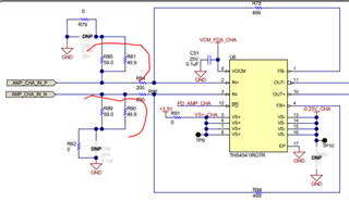
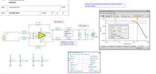
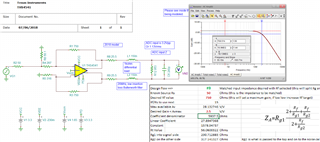
We are using THS4541 in our front-end circuitry for driving the inputs for the ADC. It takes a single-ended input and provides a differential output in our use case. The theoretical noise floor of the ADC is around 85 dBFs and the ADC expects a full scale input of 3.2Vp-p. The THS4541 is being supplied with rails of +3.3V and -0.23V. We are checking system (input driver+ADC) performance at input frequencies of 10KHz, 250KHz and 2MHz with sampling frequencies ranging from 10MSPS to 50 MSPS. At lower frequencies we are satisfied with the performance: an SNR of around 83 dBFs, HD2 of nearly 100 dBc and HD3 of nearly 90dBc. But at 2MHz, although the same SNR and HD2 can be obtained, HD3 drops to 75 dBc. 

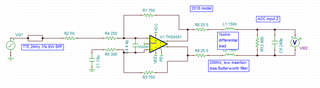
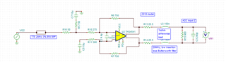
Based on the datasheet plots, we understand that the amplifier needs to see large differential output loads, works better at output swings of nearly 2Vp-p and at lower input frequencies. Given our need, we have designed some circuitry around the THS4541 to meet performance requirements. 

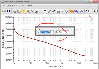
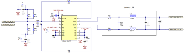
  • There is a 20MHz LPF to bandlimit the noise at the output of THS4541
  • The amplifier also sees a 100pF differential load at its output as part of a filter needed to prevent the sampling kickback from reflecting as a glitch at the input
  • The input common mode is set through the device VCM pin using two 200 ohm resistors

I have attached pictures of our input circuitry with some changes as listed below, please go through it and suggest changes that can help improve HD3 performance at 2MHz without causing a drop in HD2 or SNR.

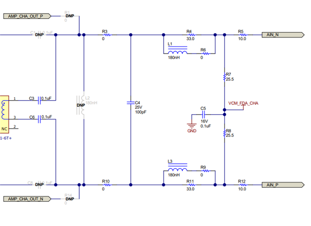
R79 and R92 are replaced with a 10uF cap to ground. R81 (50 ohms) is removed. R7 and R8 are replaced with 200 ohms. The input to amplifier is given from SMA100A with 50 ohm source impedance.

  • Well, a couple of things Akash, 

    Not sure why you have such a heavy input termination, that might be causing HD at the inputs, Lighten that loading up if possible, 

    HD3 is largely loading, you can lighten that up (with a bit higher noise) increasing the R values, 

    Also, here is an alternate filter type that I have found works very well. Sometimes splitting that last cap and adding some part of it as a cap to ground on each ADC input helps the glitch suppression. 

    Here is this file, 

    THS4541 2018 model gain of 2.5 with filter to ADC.TSC

  • Hi Michael,

    Thank you for taking out the time to respond. Based on your inputs, I have tried the following two configurations:

    We are driving the amplifier single-ended from a SMA100A signal generator of 50 ohms source impedance. The input side termination was to get symmetry on both P and M side of input with respect to the resistance seen by the AC input.

    For this, I obtained a HD2 of around 95-98 dBc, HD3 of 75dBc (no change so far with respect to what we were using earlier), but the SNR dropped to 75dBFs from an earlier value of 83dBFs. Have I misinterpreted your suggestion somehow? 

    Also, the sampling glitch doesn't seem to be filtered effectively. There are artefacts on the input to the ADC that disappear upon switching off the sampling clock. I do not have very clear images of this as I am currently limited by the bandwidth of the scope and probe I'm using.

  • Your input networks are not correct, 

    You need to read that section in the THS4541 datasheet in input impedance matching for single to differential conversion, it is sadly very complicated due to the active input impedance nature looking into that side of the Rg elements, but all the equations are there, Section 9.4.1.4, 

    Here is the correct setup for the inputs, using 750ohm Rf still - also, get rid of that 4pF across the input pins for now also, can use that later if need be, 

    Here is the SNR simulation at the ADC inputs, 85.6dB. 

    And this updated file, 

    6472.THS4541 2018 model gain of 2.5 with filter to ADC.TSC

    And, yes, if you are using a BP filter you will need to AC couple R5 and R6, but it would be easier if you changed to a low pass filter. Then you can be DC coupled in the FDA and be sure of balance,