This thread has been locked.

If you have a related question, please click the "Ask a related question" button in the top right corner. The newly created question will be automatically linked to this question.

INA321: Amplification issue uA

Part Number: INA321

Hello,

I have been asked to review a scheme that uses the INA321EA.

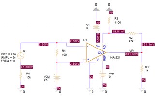
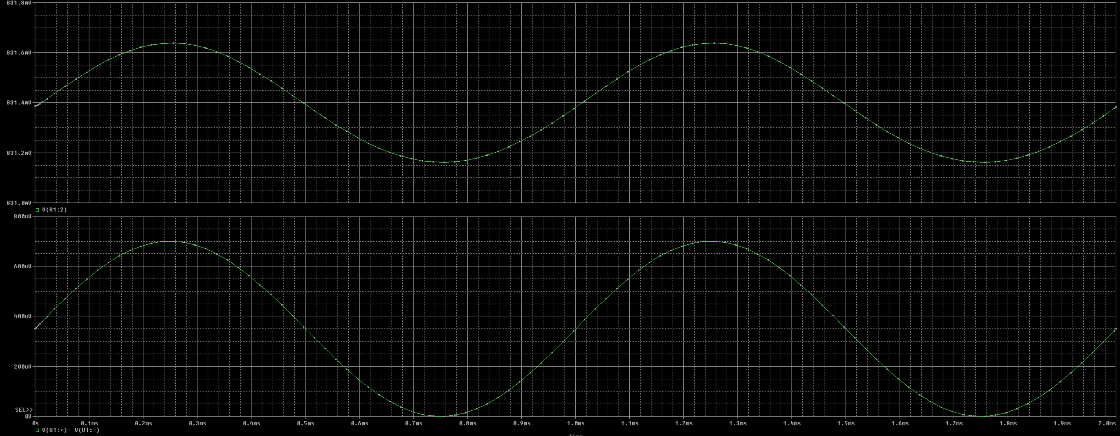
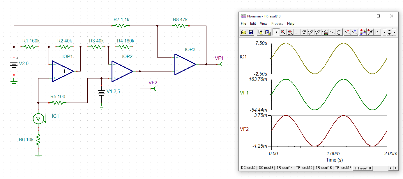
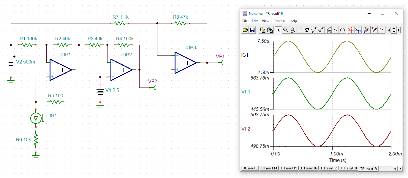
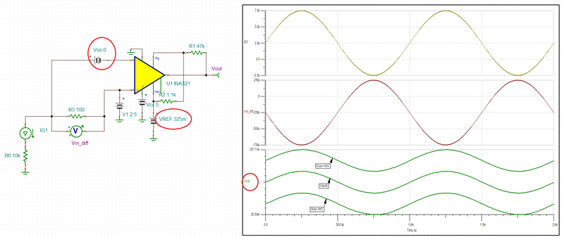
The problem is that the output of the INA321 does not always have the same output voltage on different printen circuit boards in production. The component is used to measure the current flowing through R4 (100 ohm) (max 7uA) The circuit has been simulated in PSpice, but here I don't see the same result as in practice. (practice INA321EA max. output = 350mV)

Is it possible that a mistake has been made here, and that the Input Offset Voltage of the INA321 is not achieved.

Thank you for the assistance

  • Hi Joris,

    you force the internal output of A2 of INA321 to go all the way down to 0V which the INA321 is not able to do:

    You better introduce a suited pseudo ground, here 0.5V (just an example Relaxed):

    joris_ina321.TSC

    Kai

  • The output of the INA321 varies because your differential input voltage is of the same magnitude as the INA321 input voltage offset, Vos=+/-1mV.  Since the gain of the circuit is high (G=~218), you must calibrate out the effect of the input offset - see below. This is also the reason why you need to use Vref>325mV so the output, Vout, never falls below the minimum linear range of 50mV above the negative rail.

    joris_ina321+Vos.TSC