Hi team,

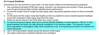
I don't understand the fifth point in the screenshot of datasheet above. How does it work? Could you please elaborate it? Does the impedance mentioned here refer to the impedance of this small capacitor?
Best Regards,
Amy Luo
This thread has been locked.
If you have a related question, please click the "Ask a related question" button in the top right corner. The newly created question will be automatically linked to this question.
Hi team,

I don't understand the fifth point in the screenshot of datasheet above. How does it work? Could you please elaborate it? Does the impedance mentioned here refer to the impedance of this small capacitor?
Best Regards,
Amy Luo
Hi Amy,
I believe what was meant was that generally speaking, the board is flooded with a ground pour on the top and bottom layers so providing some additional coupling between the outputs and inputs is recommended. The impedance mentioned is referring to the impedance of the source of the input signal; its common that it is not a low impedance source.
Hi Chi,
Thank you for your reply. But I don't understand what you said. Isn't the fifth point about preventing parasitic feedback? But you said that providing some additional coupling between the outputs and inputs. Isn't that contradictory?
so providing some additional coupling between the outputs and inputs is recommended.

The impedance mentioned is referring to the impedance of the source of the input signal; its common that it is not a low impedance source.
How to calculate the propagation delay time? Could you please provide some guidance
Best Regards,
Amy
Hi Amy,
point 4 of the layout guidlines is a bit misleading. I try to say it with my words and use simulations with the TLV3801.
Try to avoid any parasitic capacitive feedback from the output to the negative input of comparator because this can cause instability and oscillation:
Without capacitive feedback everything is ok, even if the source impedance is a bit high (R1 = 10k):

But with a small capacitive feedback caused by stray capacitance (C1 = 1pF) instability occurs:

The reason for instability is very simple: When the output toggles, C1 is lifting the -input of comparator into the wrong direction and by this sabotages the toggling. You would want to see just the opposite or at least that the potential at the -input is not influenced by the output signal of comparator. What you see is the oppositie of introducing hysteresis.
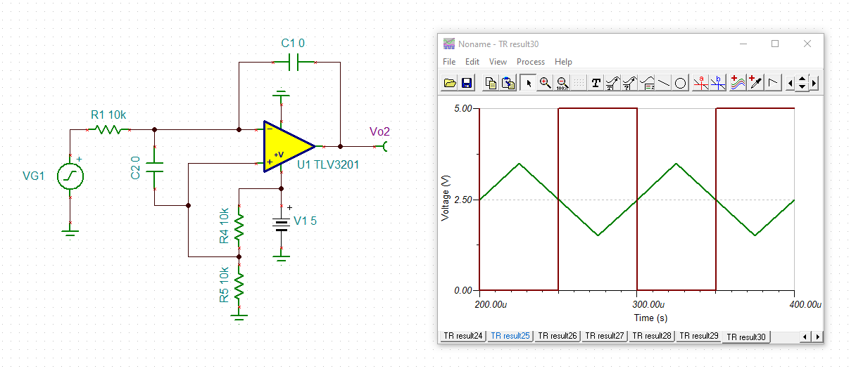
One remedy (not recommended) is to mount a cap between the inputs:

By this a voltage division takes place (C1 and C2) which decrases the fedback edge from the output so much that no mistriggering occurs any longer. But look how the threshold voltages are shifted and how much capacitance is necessary to do the trick.
Another remedy (not recommended either) is to mount a cap from the -input to ground:

Again a voltage vision takes place which prevents mistriggering any longer.
A way better remedy is to keep the source impedance low ohmic and by this to introduce sufficient voltage division:

Or by avoiding or at least mnimizing the parasitic stray capacitance from the output to the -input as shown in the first simulation.
And now comes the layout guidlines into play: If you have two copper tracks separated by a certain distance, here the input lines to the output lines, then you have a certain parasitic capacitance between them. But if you place a ground plane or at least a ground pour or ground fill between them, you can heavily decrease this parasitic capacitance, because the majority of field lines no longer go directly from the input lines to the output lines and vice versa, but from the lines to the ground plane. Only a very small portion of the electrical field lines jump between the input and output lines any longer which -in terms of electrostatics- means a heavily decreased coupling capacitance.
This is why a solid ground plane is so helpful in HF circuits. It does not only provide a very low impedant ground potential reference for all signals but it also very effectively shield signal tracks from each other. But keep in mind that a ground pour or ground fill on the top layer can only act as an effective shield when the ground pour is connected to an underlaying solid ground plane by as many vias as possible.
Let me add a word: It's never a good idea to slow down the input signal traversing the susceptible threshold region of a comparator. This is counterproductive and should be avoided by all means. That's why I would not recommend to mount this input capacitor. Just the opposite is correct: Speed up the traversing by introducing hysteresis!
Keep the source impedance minimal, use a layout with a solid ground plane and ground fills, add a proper supply voltage decoupling and add hysteresis and the comparator will never fail
Kai
Sorry Amy. I had meant to say providing some additional isolation to minimize coupling between the output and inputs is usually recommended. Seems like a few words was cut out there. Nevertheless, kai's points are valid and having a solid ground plane and pour are good techniques.
The propagation delay is the time required for the comparator output to reach 50% of its final output level when the input changes to 50% of its final input level.
Hi Kai,
Thank you very much for your analysis that you made about this. It’s useful.
Hi Kai & Chi,
With regard to propagation delay, why is the propagation delay longer when the signal source impedance is small? Could you please help to analyze this

Best Regards,
Amy Luo
I believe Amy was referring to when the cap is between the inputs but essentially as you traverse through the transition region that means now the output toggles a slightly shifted later point so the response delay from the input to output is slightly longer.
Hi Kai,
Thank you very much for everything you have done and given your time for this.
Hi Chi,
According to Kai's simulation analysis results, this description (This capacitor causes some degradation to propagation delay when impedance is low. ) in the datasheet is the opposite of the simulation results. Is it necessary to make corrections to the datasheet to avoid misleading other users?