This thread has been locked.

If you have a related question, please click the "Ask a related question" button in the top right corner. The newly created question will be automatically linked to this question.

INA333: Simulation not matching expected results

Part Number: INA333
Other Parts Discussed in Thread: TL331, TLV3501

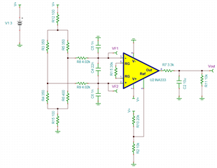
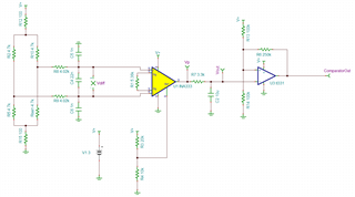
I'm simulating the INA333 in TINA TI. The amplifier will be sensing a wheatstone bridge. 

My circuit generates a differential voltage of 0.06V. The expected output is:  + ref

Where: 

Gain = 1+ 100k/5.36k = 19.65

Therefore Vout = 19.65 * 0.06V + 1 = 2.179V.

The circuit includes a common noise filter at the input.

Additionally, R12 & R15 aim to keep the signal away from the supply rails.

Are there errors in my schematic?

INA333 Test.TSC

  • Hi Dylan,

    Are there errors in my schematic?

    Here are my comments:

    1. I always download the latest PSpice model from our website. Your PSpice model is released in 2011. I think that the old INA333's model is ok, but the schematic should connect Vin+ on top and Vin- on the bottom. In other words, Vdiff input should be positive for the single supply rail configuration.

    https://www.ti.com/product/INA333#design-tools-simulation

    2. Ref pin requires low impedance node as shown in the simulation below. When voltage divider is placed at the Ref pin, it will disturb the A3 difference op amp's gain balance and resulted errors at the output. So Ref pin needs to be a low impedance node (with source/sink in current low impedance output).  

    3. 64.42mV would be the differential input voltage based on the simulation, see the attached file. 

    4. The Vcm input voltage is configured correctly, but you may consider to simplify the configuration. 

    Please down load the Analog Engineer's calculator, and it may help you to configure the instrumentation amplifiers and other TI products. 

    https://www.ti.com/tool/ANALOG-ENGINEER-CALC

    Below is the Tina simulation file. 
    INA333 Test 03132023.TSC

    If you have additional questions, please let us know. 

    Best,

    Raymond

  • Thanks Raymond, you're right, the new model fixed the issue.

    Can I ask an additional question? I'm trying to add a simple comparator on the output of the INA333.

    I'm using the TL331 (Actually using the TL391 for design) but it doesn't seem to be working correctly with 3V supply.

    I'm using two 100k resistors to create 1.5V as the comparator reference point.

    It switches at the right point but from 1.5V to 1.5V instead of to 0?

    Sensor Interface Sim - Resistor Ref.TSC

  • Hi Dylan, 

    I think that you need to pick a low voltage comparator instead. It works with TLV3501 comparator. TL331 or TL391 will not work for 3Vdc rail, see the Vcm comparator's requirements below. 

    Sensor Interface Sim - Resistor Ref 03142023.TSC

    I mentioned that you have to use low impedance node for Ref pin. Op amp's Vout is considered low impedance node, so are bandgap references. 

    Enclosed is the link that you should be able to find our comparators in TI E-store. 

    https://www.ti.com/amplifier-circuit/comparators/products.html?keyMatch=TI%20COMPARATOR#sort=p358min;asc

    If you have other questions, please let me know. 

    Best,

    Raymond