


Hi,
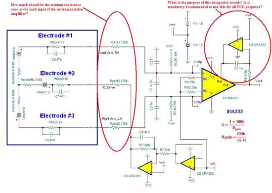
I was looking at a long chain of threads talking about how the reference voltage of the INA333 is set by a voltage divider followed by a buffer and an Integrator circuit.
However, I really haven't understood the importance of the circuit, and whether it is mandatory/recommended to use it. Could someone explain this concept, direct me to a link where this factor has been explained?
Further, what is the recommended input resistance value at each input of the In-Amp for an ECG circuit? (I have attached an image of a circuit used in an older thread, and have highlighted my queries with red circles)
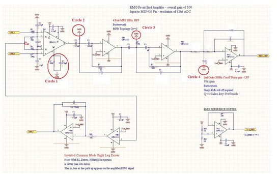
Also, I had certain doubts about a circuit, that was posted later on the same link. I have attached the image of that circuit below for reference.
1. The First stage in this circuit has an IN-AMP which has been referenced to ground, and furthermore, is single supply. So if I understand the circuit correctly, the output of the INAMP will be half wave rectified?
2. Also, now let us assume that the reference pin of the INAMP was given VCC/2 thereby shifting the entire ECG signal by +VCC/2 volts( i.e biasing the ECG signal at half supply). Will the filter stages that follow be referenced to VCC/2 volts in that case? I mean (referring to the figure below) will the GND points in circle 2, circle3 and circle 4 be replaced by VCC/2 points? Or will the Circle 4 GND point remain where it is (since it is the final stage of the circuit, and we want our final signal to be referenced to GND)?
Thanks a lot,
Yash

