This thread has been locked.

If you have a related question, please click the "Ask a related question" button in the top right corner. The newly created question will be automatically linked to this question.

THS7316: Enhance VGA signals quality

Part Number: THS7316

Hi,

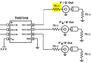
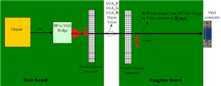
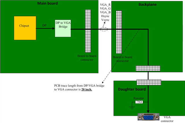
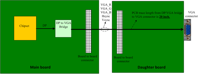
Do you recommend the solution to enhance VGA signals quality of R,G,B, Hsync and Vsync due to PCB transfer of board to board connector and long PCB trace length(20 inch).

See the following picture for detail connection.

Thanks!

Chin

  • Hi Chin,

    Thank you for the diagram. When moving signals between boards, special consideration should be taken. Overall PCB layout recommendations are to place the device as close to the next element in the design as possible. I have a few questions to help give the best recommendation.

    Is there a design requirement which necessitates having a main board and daughter board? If so, can you clarify what connector is being used between boards? 
    Are you experiencing a signal integrity issue during your testing?

    A few other comments - when working with video signals over long distances, it is important to observe impedance matching. The diagram below from the first page of the datasheet demonstrates this with a 75 Ω passive series resistor directly at the output of the amplifier. The cylindrical element after represents any length of cable line, which in this situation would be your inter-board connector, which should then be terminated by another 75Ω resistor.

    Additionally, it is important that the inter-board connector and board traces also have 75Ω impedance matching. I have drawn on the diagram provided to help illustrate this information. 

    Thank you,
    Rachel

  • Hi Rachel,

    Thank you for your feedback.

    The product of following website is the board to board connector that we use in the design

    https://catalogs.glenair.com/view/672410322/4/

    I have to update more clear picture of our VGA signal architecture,see following picture.

    Based on this architecture, we connect the VGA display and it have distortion(shadow) issue , see following picture.

    It seems to me that THS7316 can solve the issue ? 

    For the 75 impedance , does it just relevant to R,G,B three signals ? how about the impedance of  Hsync and Vsync?

    Sincerely,

    Shichin

  • Hi Shichin,

    if you want to achieve highest performance you cannot go this way. You have breaks in the characteristic impedances of lines between the "DP to VGA bridge" and the monitor. Breaks occur on the main board, on the backplane, on the daughter board, on every connector between and finally on the VGA connector itself. Every break means the generation of an echo which may totally ruin your signal integrity.

    The whole line between the "DP to VGA bridge" and the monitor must have the same characterisitic impedance. And if the VGA cable has a chracteristic impedance of 75R then the whole line must have a characteristic impedance of 75R as well.

    Keep in mind that at the output of "DP to VGA bridge" there must be mounted 75R series termination resistors. And at the input of monitor 75R resistors must be mounted from each signal line to ground. Between these termination resistors the whole line from the "DP to VGA bridge" to the monitor must have a characterisitc impedance of 75R too.

    This means that there must not sit an additional 75R resistor from each line to signal ground in your device. This also means that you have to choose a layout for all the video signals on the main board, the backplane and the daughter board that provide a characterisitc impedance of 75R. This means that you must carry out these lines in microstrip or stripline technique.

    Another remedy is that you mount a VGA connector directly at the output of "DP to VGA bridge" (behind the 75R series termination resistors !) and that you mount a VGA cable from this VGA connector to the VGA connector on the daughter board, so that the video signals run through a VGA cable now and no longer have to travel over the backplane and through all the non-video board-to-board connectors.

    And yes, when you run the Hsync and Vsync signals through a 75R cable you will need 75R termination resistor for them as well.

    Kai

  • Hi Kai,

    Thank you for your expert suggestion!

    Because all the boards need connect via board to board connector so we cannot use VGA cable to link the boards.

    Besides the matching 75 ohm impedance, do you think THS7316 is an option to be added in such length connection to improve signal integrity ?

    If the answer is yes, how about Hsync and Vsync signals? needed as well?

    Thanks!

    Sincerely,

    Chin

  • Hello Chin,

      Typically Hsync and Vsync singals are very low frequencies which means impedance matching shouldn't be an issue for these signals. If signals are under a few MHz, then total length of 20inches will not be an issue. 

      This article has a table of cable length threshold vs signal frequency to prevent reflections. 

    Thank you,
    Sima

  • Hi Sima,

    Thank you for your comment and the good article!

    Sincerely,

    Chin

  • Hi Chin,

    I don't know what you use in the box "DP to VGA bridge" and I don't know whether you need an additional low pass filter in the signal chain either. If there are already 75R video drivers at the outputs of "DP to VGA bridge" then you would not need an additional THS7316.

    In any case, you will urgently need to use microstrip or stripline technique on the "main board", the "backplane" and the "daughter board". But even then, because you have so many non-video board to board connectors in the signal path, you may not achieve highest performance.

    I would be careful with the Hsync and Vsync signals. Allthough the bandwidth seems to be somewhat lower compared to the RGB video signals, clean edges of the Vsync and especially the Hsync signal may be important for proper triggering. I have seen some applications where unwanted echoing on the Hsync signal due to imperfect cable termination caused issues.

    Also, using properly terminated cables means much more than the avoidance of unwanted reflections (echoing). Only in a properly terminated cable the wave packet is running entirely inside the cable (coax cable, microstrip, stripline, etc.) and no portion of the wave packet is leaving the cable and is partially running outside of cable. So, using properly terminated cables is also essential to isolate HF signals from each other which are running close to each other like in your "RGB + Hsync + Vsync" application. So, I would use a 75R termination for the Hsync and Vsync signals as well.

    Kai   

  • Hi Kai,

    Okay, understood!

    Thanks for your suggestion!

    Sincerely,

    Chin

  • Hi Kai,

    We also measured VGA signals (see atatched), do you think whether the shadow image was caused by the over shoot of measured signals?

    Does THS7316 can solve the issue ?

    Shadow image.docx

    Sincerely,

    Chin

  • Hi Chin,

    when you run the RGB-signals and SYNC-signals differently (with and without cable termination) then you will get different delays for the signals and the synchronization can suffer. Because of that, it's important to treat the RGB-signals and SYNC-signals exactly the same way and to use proper cable termination. So, I would use for all signals exactly the same driver, the same termination and the same microstrip or stripline construction.

    And you can very nicely see in photo Nr.5 the ringing of RED-signal shown in photo NR. 3. This is the direct consequence of improper cable termination of involved signals.

    And in photo Nr.1 the unwanted crosscoupling between the HSYNC-signal and the RED-signal can be seen. This crosscoupling is also a direct consequence of improper cable termination of involved signals.

    I like very much your photos, because they very well demonstrate what is going wrong in your application. And they show you that improving the cable termination will solve all your problems Relaxed

    Does THS7316 can solve the issue ?

    Can you show what you have in your "DP to VGA bridge"? Are there already 75R drivers?

    Kai

  • Hi Kai,

    Attached is the schematic of DP to VGA bridge,, FYI.

    By the way, so from your point of view, the shadow image issue is caused by cable termination mismatch and we don't need to add THS7316 buffer chip to enhance RGB signals driving strength because of longer pcb trace routing? 

    Thanks!

    Shichin

    DISPLAY TO VGA.pdf

  • Hi Shichin,

    I would try to connect a 75R resistor from each output (RGB, HSYNC and VSYNC) to signal ground. In combination with a DAC providing current outputs this should give a 75R source termination. Connect the cables directly to the DAC outputs (with the 75R resistors to signal ground) then and have 75R resistors only at the end of 75R cables, at the monitor side.

    For this experiment I would think about removing all the many filtering caps and filtering inductances shown in your schematic, since these can cause additional and unwanted signal delays.

    Kai