Other Parts Discussed in Thread: LMH2110
Hi,
Good Day.
I am trying to understand in LMH5401, what kind of DC gain I am going to get and also what kind of gain I can have if the input is an 8GHz RF signal.
This thread has been locked.
If you have a related question, please click the "Ask a related question" button in the top right corner. The newly created question will be automatically linked to this question.
Hi,
Good Day.
I am trying to understand in LMH5401, what kind of DC gain I am going to get and also what kind of gain I can have if the input is an 8GHz RF signal.
Hi Ray,
Your DC input common mode will be rejected by LMH5401and output common mode is set by VOCM pin.
For your 2nd question about AC output for 8GHz -10dBm sin wave, It depends on the gain config you have set on LMH2110. You can refer to Fig 56, Fig 57 and Table 1,Table 2 under sec 7.3 of datasheet depending on your input single ended/ differential ended. Please do remember to see the freq response plot for given gain in Fig 1 and Fig 2 and you could see gain rolls at 8GHz.
Best Regards,
Hruday
Hi Hruday,
Good Day.
Your DC input common mode will be rejected by LMH5401and output common mode is set by VOCM pin.
For your 2nd question about AC output for 8GHz -10dBm sin wave, It depends on the gain config you have set on LMH2110. You can refer to Fig 56, Fig 57 and Table 1,Table 2 under sec 7.3 of datasheet depending on your input single ended/ differential ended. Please do remember to see the freq response plot for given gain in Fig 1 and Fig 2 and you could see gain rolls at 8GHz.
Hi Hruday,
Good Day.
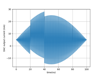
For example, if at the differential input, I have a signal as attached, which contain

Hi Hruday,
Good Day. I would like to follow up on the latest customer's query. Thank you very much.
Hi Ray,
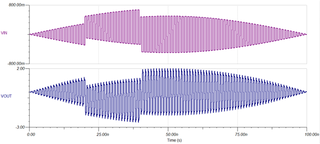
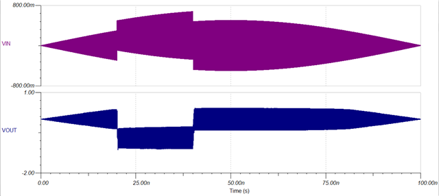
Thank you for your patience. I got a chance to simulate in TINA TI for the input wave form you provided and below is what the output looks like for gain = 4V/V. for 1GHz, 7GHz
1GHz:
7GHz:
sbom919b (2).TSC
At 7GHz you could definately see the Gain reduces as expected from datasheet. I am also attaching the TINA sch file.
Regards,
Hruday