This thread has been locked.

If you have a related question, please click the "Ask a related question" button in the top right corner. The newly created question will be automatically linked to this question.

OPA4348: Problem with possible Latch-Up

Part Number: OPA4348
Other Parts Discussed in Thread: UCC29910A, , LM2902

Hello,

we are currently designing an 1.7kW 48V-ACDC Converter.
The Input to the Converter is three-phase AC between 200V and 308Vrms on each of the phases.

For the PFC-Stage we are using UCC29910A, to step the Input Voltage down to 300VDC.
Measuring the Output Voltage of the PFC and Scaling for UCC29910A to work correctly is done with a difference Amplifier using OPA4348.
Two Amplifiers are used as buffers, as to not load the Voltage Dividers.

Schematic see picture below:

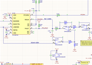
Converting the 300VDC into 48V is done using an LLC-Converter with ONsemi NCP4390 as Controller.

Both the PFC and the LLC by themselves work fine.
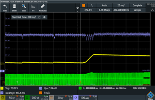
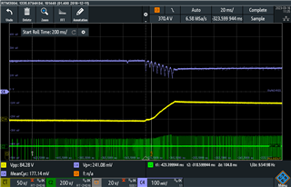
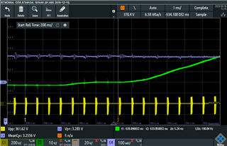
If we run the complete PCB, while increasing output power to ~50W, we run into the problem, that the Output Voltage of the PFC would sharply increase close to 400VDC.
We do have an overvoltage protection in place, which triggers the Fault-Input of the PFC and turns everything off.

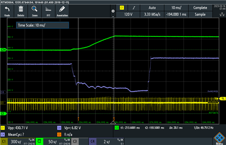
We found, that the error was caused by the output of OPA4348 going low, thereby telling the PFC-Controller, that its output voltage was too low.
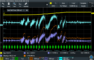
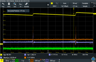
The blue trace shows the output of the Difference Amplifier, the green trace is the output voltage of the PFC, yellow is the primary side of the LLC-Transformer.

We checked the Input Voltages at the buffers, as well as the supply voltage for OPA4348, but none of those measurements have shown any obvious errors.
OPA4348 was also exchanged for an LM2902 powered by a 9V-Battery, to see if that changes anything.
in fact, that solved the problem, as long as the PCB was not mounted on the heatsink.
With the PCB on the Heatsink, even LM2902 shows this error.

We do not have much space to work with, so everything on the PCB is pretty close to everything else.
Therefore we thought about EMI being a probable cause for our Problem.
But then we would have expected to see an error occuring with every switching cycle of either the PFC or the LLC, not one error persisting for 40ms.

Can this be explained by an Latch-Up inside the OPA4348/LM2902?


  • Hallo Fabian,

    can you tell me the signal range of the blue signal in the scope plot? Is it within the supply voltage of OPAmp?

    When you carefully look at the scope plot you will notice that the blue error signal seems to be synchronized with the yellow signal. So, there seems to be some unwanted coupling.

    Since the VBULK signal is low pass filtered (R151 and C151) I would add some more filtering caps to the circuit. R152 and R155 could profit from identical caps mounted in parallel to them. Take something in NP0 with very low tolerances.

    Then the signal at pin 10 of OPAmp could also be low pass filtered.

    I don't think that you see latch-up. Latch-up is something that locks-up the OPAmp and can only be resolved by turning off and turning on the supply voltage again. It looks more like a damaged chip or damaged passive component. I would replace C151 by a fresh one. Are you sure that the PFC chip is ok?

    Soldering issues can also look this way. Have you checked that the printed circuit board is properly soldered, washed and dried?

    Don't connect the scope probe directly to the output of an OPAmp. Insert an isolation resistor of 100...220R or so first. And use such a ground spring when probing:

    Viel Glück,

    Kai

  • Hello Fabian,

    Could you also provide scope captures of what the input values are to the difference amplifier? Additionally, unless the heat sink is connected electrically to some components, adding it should not change the performance of the board. Additionally, what do the voltages at the power pins look like? Is there a ground bounce when the power increases? 

    Best,
    Jerry

  • Hello Kai,

    The signal range of the output is 400mV/div. The Output-Voltage at the beginning beeing the 1.048V UCC29910A regulates to.
    The Supply Voltage of OPA4348 is 3.3V.

    Unwanted Coupling was also a probable cause we were thinking about, but we could not explain, why the Output of OPA4348 would stay low for almost 40ms and not somewhat recover in between switching cycles of the LLC. 

    Both Inputs of the Buffers (Pins 10 and 12) are filtered the same, it just got cut away, when i took the picture.
    C151 has been replaced, as well as all the filtering capacitors on the input of the Buffers.

    The Solder Joints for both OPA4348 and UCC29910A have been checked optically and with continuity measurements for each pin. Both looked and measured fine.

    The PFC-Chip seems to be working correctly as well. Both the Voltages at VBULK and LINESNS are as expected and the ratio between those 2 pins is 4:1, as described in the datasheet.
    Also FAULT triggers correctly, since switching stopps and UCC29910A goes into it's latched fault state, once we have overvoltage on the PFC-Output.

    The measurements at the OPAmp are done using an optical Langer-Probe, soldered directly to the pins of the Amplifier.
    Measurement of the PFC-Output Voltage and LLC Transformer Primary are done using HV-Differential Probes.

    I will try doing the measurements with a Probe+Ground Spring again.
    I will also place some capacitors parallel R152 and R155.

    Thank you for your help!

    Fabian 

  • Hello Jerry,

    the heatsink is connected to PE.

    Pictures 1 and 2 show the input signals to the Buffers (blue), the PFC-Output Voltage (yellow) and the Switch-Node of the LLC (green).
    Picture 1 is the input to the LINESNS-Buffer at pin 10. Picture 2 shows the input to the second Buffer at pin 12.

    From what i can tell, the signals seem fine. The voltage difference between both is close to 262mV.

    Picture 3 shows the outputs of both Buffers. The orange trace showing the signal at pin 8. The violet trace is pin 12.
    Yellow is the Output of the PFC and green is the switching of the LLC.
    The light blue trace is the difference between both outputs of the buffers. So this should be 1.048V/4 = 262mV.
    Which it is, as long as the Op-Amp operating normally. But as soon as the error is triggered, both outputs of the buffers are wrong.


    The noise seen on the violet trace is the 100kHz switching noise of the PFC.
    We thought, that the LLC switching is causing this problem, but from the output signals of the buffers it does not seem to correlate, since the outputs do not always rise, when the LLC starts a burst.
    Interestingly the outputs of the buffers only then drop, when neither PFC, nor LLC are switching. But instead of recovering, they both fall to GND most of the time.

    The voltage at the power pins of the OpAmp looks fine. There was a litte bit of ringing, but after we put another 2.2µF on the power rails, this was gone.
    There 

    Thank you both, for your help!
    Fabian

  • Hi Fabian,

    OPA4348 was also exchanged for an LM2902 powered by a 9V-Battery, to see if that changes anything.
    in fact, that solved the problem, as long as the PCB was not mounted on the heatsink.
    With the PCB on the Heatsink, even LM2902 shows this error.

    This makes me think, that it doesn't have to do with the OPAmp itself. A different OPAmp with a totally different internal circuit would not show exactly the same error.

    Having to do with the heatsink mounted or not could mean that mechanical forces have to do with the error. A defective component or defective printed circuit board could behave exactly that way.

    The signal suddenly becomes chaotic seemingly without any reason and recovers a bit later again seemingly without any reason. This also makes me think that a defective component or a defective printed circuit board is the cause for error.

    I would run tests with a fresh board.

    Kai

  • Hello Kai,

    so, we did run a fresh PCB with OPA4348 yesterday. The PCB was layed on the Heatsink, but not screwed on as to prevent any mechanical forces.
    Both PFC and LLC start up fine, but while increasing power, the same problem occured again.
    So, to us it does not seem to be a problem related to a part beeing mechanically damaged.

    With the new PCB we also found, that this problem seems to happen on the regular.
    Whenever UCC29910A starts switching in Burst-Mode, while running in low power conditions, the output of the Buffers is wrong.

    The PFC shutting off, seems to be caused by the Buffers beeing "more wrong" at some Bursts than others.
    Therefore the voltage rises longer and triggers the Overvoltage Protection.

    Fabian

  • Hi Fabian,

    So, to us it does not seem to be a problem related to a part beeing mechanically damaged.

    Excellent test Relaxed

    Then I think it could actually have to do with EMI. You already mentioned:

    We do not have much space to work with, so everything on the PCB is pretty close to everything else.
    Therefore we thought about EMI being a probable cause for our Problem.

    Now I would experiment with the add of some EMI shielding. By the way, Is the heatsink connected to signal ground or another suited potential that allows it to work as a shield instead of an antenna injecting noise? This could explain why things become worse when the heatsink is mounted.

    Kai

  • Hi Kai,

    the heatsink is connected to PE, since it may be possible to be touched.

    We did try shielding the control circuitry by surrounding the LLC-Transformer with a copper shield connected as close as possible to the "ground" of the PFC-Output, as well as the PFC-GND. 
    Since the Problem with LM2902 only happens, when the PCB is placed on the heatsink, we also tried shielding the OpAmp, by surrounding it with a copper shield connected to PFC-GND on all corners.

    Both tests did not change anything in the behaviour of the OpAmp.

    It seems that there are multiple factors, that need to be present for the problem to happen.
    If the PFC runs by itself and the LLC is disabled, it runs fine, even on the heatsink.
    If the PFC and the LLC run, and the LLC is forced into resonant mode by quickly increasing the load, then everything is fine aswell.
    If the PFC and the LLC run, and there is no Load the LLC runs in a Burst-PWM-Mode to increase light load efficiency. Then everything works aswell.
    But if both converters are running and the Load is slowly increased, the problem occures. But then, it seems, as if the wrong output of the Buffers is somehow triggered by the PFC starting a Burst.

    What we are still wondering is, why the OpAmp does not recover at all. Even when neither the LLC is switching and the PFC is doing a burst.
    In that case, the circuit should mostly be quiet.

    Fabian 

  • Hi Fabian,

    have you thought about using some Y-caps to connect PE to circuit ground? This would turn the heatsink into a shield.

    Kai

  • Hello Kai,

    we have Y-caps on the input side input side infront of the rectifier.
    Additionally we have a Y-cap between the secondary side of the LLC and the PFC_GND.

    Though there are no caps directly from PFC_GND to PE. 
    So i will try that.

    Thank you!

    Fabian