Other Parts Discussed in Thread: SYSCONFIG, INA229, TI-SCB, INA236
This thread has been locked.
If you have a related question, please click the "Ask a related question" button in the top right corner. The newly created question will be automatically linked to this question.


Hello Douglas,
Thank you for using the TI forum. First off, so you know, the INA239 datasheet link that you sent is out of date. Here is a link to an updated datasheet: https://www.ti.com/lit/ds/symlink/ina239.pdf
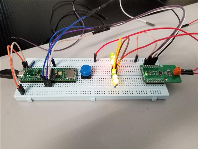
The INA239 will not function without a the GND pin connected, so if you are seeing this behavior, then there may be a hardware issue on your board. You may want to reach out to Mikroe to see if they have any ideas what could be wrong, or visually inspect the PCB for errors, such as device pins soldered together. Also double check for errors on the breadboard itself. You may want to try just connecting to the INA239 directly without a load setup to see if you can read the ID registers or the Temperature register to help validate the setup.
If you end up not getting their module to work, you may be interested in our evaluation module for the INA239: https://www.ti.com/tool/INA229_239EVM. Which pairs with this controller: https://www.ti.com/tool/TI-SCB. And evaluation is available through the GUI: https://dev.ti.com/gallery/info/CurrentSensing/INA228_229_237_238_239EVM_GUI.
Also, if you want additional software recourses, this device is available in SysConfig, which helps generate C code based on your desired configuration settings, found here: https://dev.ti.com/sysconfig/index.html?product=ascstudio&module=/ti/sensors/currentsensor/INA239
Regards,
Mitch
Thanks for replying back. I was able to read the ID register w/out the GND pin connected. I am currently in contact w/Mikroe but they have not replied back yet.
I do have a couple questions though:
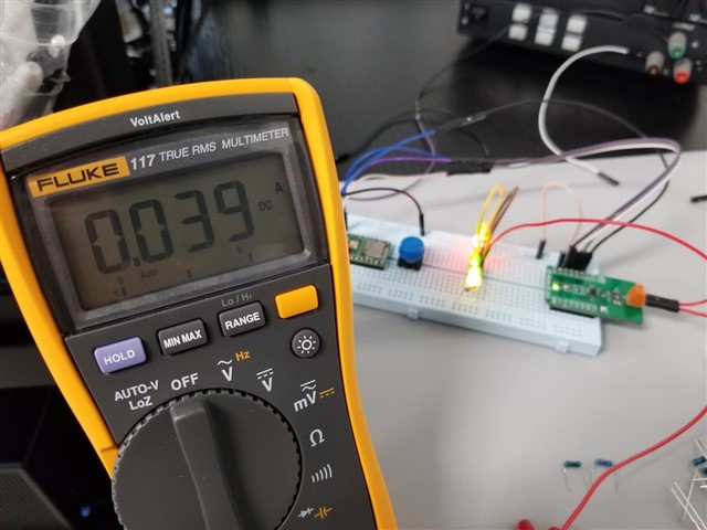
1. Does every INA239 evaluation board whether from Mikroe or TI have a max current reading of 10 amps?
2. Is your evaluation module INA229_239EVM Arduino compatible? I am currently using a Teensy4.1 board that is programmed with the Arduino IDE.
Hello Douglas,
You're welcome. Here are my responses to your questions:
1. Our INA239EVM is limited to 10A when you run the current through the PCB, but it has connections for an external shunt resistor so that you can run the current off of the PCB and use whatever current you want. The EVM User's Guide discusses how to do this in section 4.2.3.1.
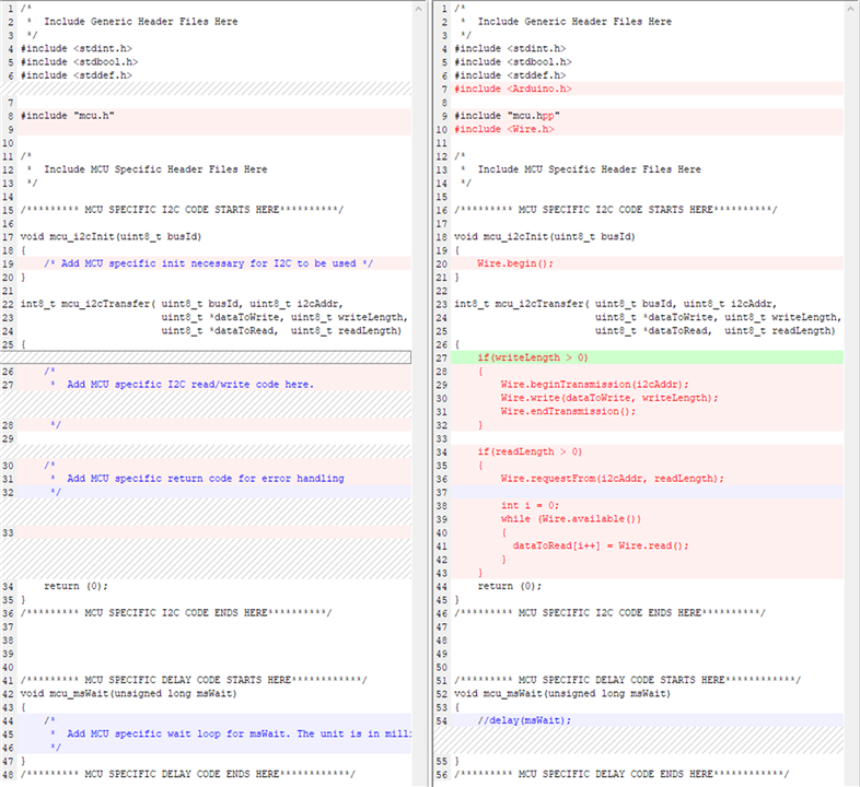
2. The INA229_239EVM (or in your case, just the INA239EVM) can be connected to whatever MCU you want. It is designed to plug directly into our TI-SCB controller that has a convenient software/GUI package ready to run, but you can always use your own MCU (like the Arduino) instead of our controller. When using your own MCU, you will have to do your own software. However, if you take the software from SysConfig, it can pretty easily be converted into an Arduino project. Here is a guide written by a colleague of mine that shows how to do this (it's written for the INA236, but will apply for the INA239 also. Click the images to enlarge them):
.
How to turn SysConfig code into Arduino code:

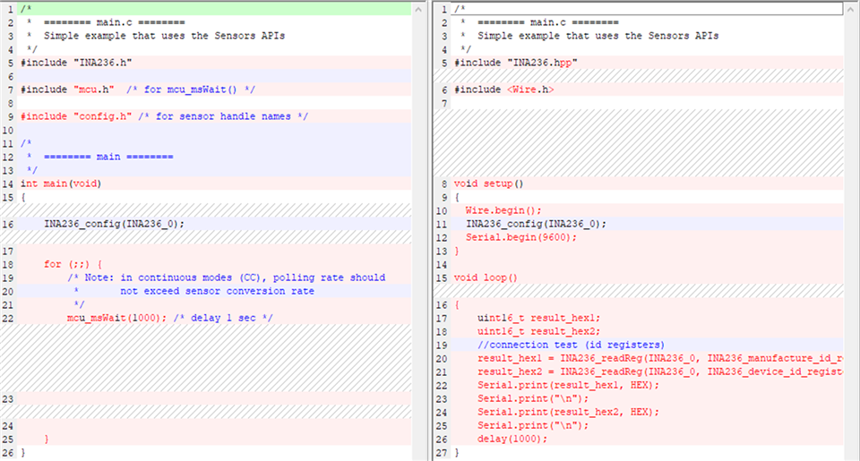
Regards,
Mitch
Thank you Mitch for the reference.
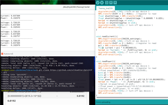
May you help me look further into the INA239 chip? I purchased some INA239 chips by themselves and decided to further test them on their own on a small 10 pin breakout board. I did not add any capacitors or resistors to the circuitry. I wired the INA239 to my controllers SPI pins and still the GND of the INA239 interferes with the accuracy of the reading. When the GND pin is connected I read 0.00. When the GND pin is not connected I read 2.8V (should read 3.3V) In this case I am only reading the VBUS which is the 3.3 volts from the controller. Is there any way you could test this out on your end? I have a feeling something is wrong with the INA239 chip itself. Below are my images of the simple setup I did.
In my last post I showed the controller on the breadboard and ina239 not on the breadboard. That caused the issue I discussed with the reading of 0.00 with the GND connected, and 2.8V with the GND not connected. I just tried taking the controller off the breadboard and just directly wiring everything to the controller and the INA239 (no breadboard). Now the vbus reading is correct with GND connected. BUT... it still powers on when I take the GND pin off. I know its on because instead of reading 3.3V, it still reads 2.8V. This is mind boggling.
Hello Douglas,
Interesting, so maybe there was a problem with the breadboard itself? I'm glad you were able to get the device to work properly with GND connected.
Regards,
Mitch
Yes I think the breadboard does something. I still have a question though. When I directly connect it like this with no breadboard, I still do not understand why the INA239 is still reading a voltage value when I take the GND off?
Dear Mitch,
With the current setup of no breadboard.
Image 1 is the correct reading with the GND connected to the INA239.
Image 2 is the reading with the GND not connected to the INA239.
Is this supposed to happen?
Image 1:
Image 2:
Hey Douglas,
We do not spec the devices for when there is power but no GND, so it could just be that power is draining somewhere else. I recommend not running the device with power connected and no GND.
Regards,
Mitch