This thread has been locked.

If you have a related question, please click the "Ask a related question" button in the top right corner. The newly created question will be automatically linked to this question.

INA293-Q1: Strange behavior of a current sense opamp: INA293A3

Part Number: INA293-Q1
Other Parts Discussed in Thread: INA293

Hello!

I am using the following current sense opamp from TI: INA293A3 connected on this way:
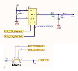
The device is working very nice from when the output of this devide is on the range from 700mV to 3.3V. I measure with the oscilloscope a very nice continues dc voltage waveform. However when the ouput of the device is below than 700mV (it means very low currents), the measurement is a square signal like the one below:
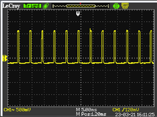
Any idea what can be the reason of such behavior? And the most important. Does anyone know how to mitigate?

Thanks in advance.

Greetings.

  • Hello Enrique,

    This I believe is due to overload recovery mentioned in the datasheet (Section 8.2.2.1).  Or the bandwidth response relative to the input voltage. (Figure 7-1 in the datasheet).

    To mitigate the one option is to place an offset at the input by placing a series resistor with one of the inputs.  The input bias current of the INA293 will then create a positive voltage at the input when the voltage at the Rshunt is 0V.  Their is an offset in the system now and a gain error that will result from this.  The offset will be likely 20µA * RSeries you add but this value will vary from device to device.  The gain error will be due to the fact that IB changes with Vsense.  

    I would say that this is the best option unless you go with our other device recently released and use the bidirectional option so the output does not saturate.

    Regards,

    Javier 

  • Helo Javier.

    Thanks for your quick answer. However I think it can not be possible that the INA293 goes into an overload condition in my desing, becuase the current can not be bidirectional....the shunt resistor is powering a TFT LED strings and the current can only goes in one direction. So it is not possible to see a "negative" voltage on the shunt....

    Could it be that the INA293 is oscillating because the current to sense is too slow and it is not able to apply the gain in the right way due to the very low voltage at the input?

    Greetings

  • Enrique,

    What is the output you expect?  Even going to GND at the output will saturate the input stage.  Also is there a spike on the VCM of the device.  Is the voltage from a PWM signal?

    Regards,

  • Hi!

    I am expecting a positive output because the input is always postive (no negative currents) and it is not close to GND. My feeling is that the opamp is working in a no stable way for currents on the range from 4mA to 15mA...and i can not believe this device is not working fine for such input positive currents... 

    Greetings 

  • Hello Enrique,

    What is the Rshunt and the VCM you are using?  Is the signal switching?  I will attempt to replicate your issue in my lab.  Have you measured the inputs to verify there is not transients.

    Regards,

    Javier

  • Hi!

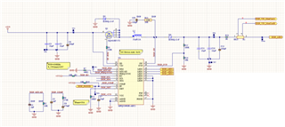
    See below the schematics of the LED driver: 

    Greetings,

  • Hello!

    I found the origin of the issue. The LED drives was working in a mix diming mode and it produced a very small ripple voltage at the output at the freq of 200Hz. This ripple voltage was magnified by the current opamp and it produces the the pulse train of the oscilloscope.

    Changing the working mode of the LED driver, reduced the swtiching noise and the output of the current opamp was totally clean.

    Thanks for the support.

    Greetings,