This thread has been locked.

If you have a related question, please click the "Ask a related question" button in the top right corner. The newly created question will be automatically linked to this question.

XTR110 responding to supply voltage and not input voltage

Other Parts Discussed in Thread: XTR110

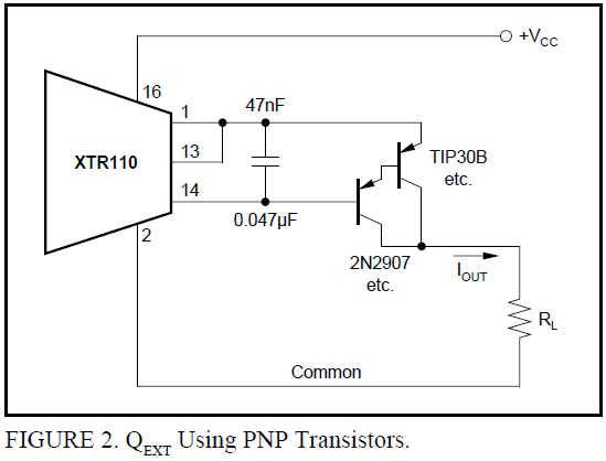
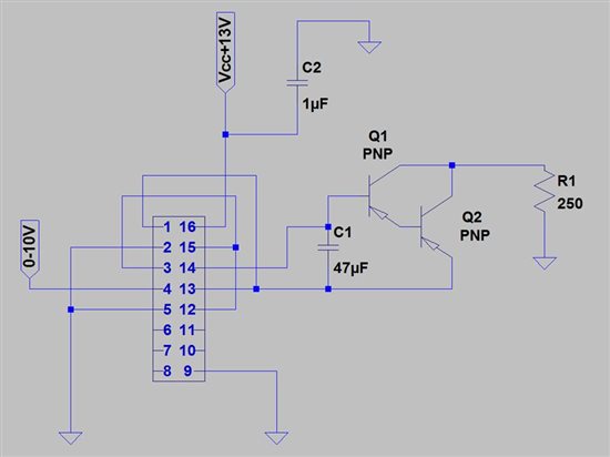
I'm trying to set up an XTR110 op amp to convert a 0-10V to 4-20mA signal for a electronic pressure regulator.  I've wired the circuit as shown in Fig. 1 of the white pages, with the substitution of two PNP transistors in place of the p-channel MOSFET transistor (as shown in Fig. 5 of the white pages).

However, when I power the circuit, the output current responds to changes in the supply voltage Vcc, and doesn't respond to the 0-10 input.

Any assistance would be greatly appreciated.

Sincerely,

Myles

  • Hello Myles,

    Thank you for the information.  Although you mention the schematic you've created is similar to the image in Figure 1 of the datasheet, would you please share a schematic of your exact XTR110 setup?  Also, please confirm that you were referring to Figure 2 of the datasheet regarding the PNP option instead of a PMOS (see image below):


    Did you include the 0.047uF capacitor across the Base/Emitter connections of the Darlington-Connected PNP transistors?

    Looking forward to your reply.

    Regards,
    Collin Wells
    Precision Analog

  • Hi Collin,

    Thanks for your response.  You are absolutely right, I meant Fig. 2.  I am using a 0.047uF capacitor.

    The above diagram shows the circuit I have built.  I apologize if its difficult to read, I do not have a background in electrical engineering.

    Thanks for your help,

    Myles

  • Hello Myles,

    The schematic you've provided shows a minimum supply voltage of 13V.  The supply voltage range for the XTR110 is +13.5V to +40V.  What is the supply voltage that you are providing to pin 16?  If you increase the supply to +13.5V or above does the problem go away?

    Also, the your text states a 0.047uF capacitor, but the schematic shows a 47uF.  Is the value in your design correct?

    Let me know what you find out.

    Thanks,
    Collin Wells
    Precision Analog

  • Hi Collin,

    The capacitor in my circuit is actually a 0.047uF capacitor, the label in the schematic is a mistake.  

    When I increase the supply voltage to ~15V, it does not fix the problem.  There is no response to changes in the input voltage.  And when I increase the supply voltage the current output increases.

    Thanks,

    Myles

  • Hi Myles,

    hank you for the additional information.  At this point I'm not too sure what is causing the issues you're experiencing in your design.  I've verified that the circuit diagram that you've provided matches the reference design in the datasheet with the PMOS replaced with a PNP darlington pair. This is a tested and verified circuit, so it's possible that you have either receieved a damaged XTR110, have inadvertently damaged the XTR110, or something is not connected in your layout the way it is drawn in the schematic.  Is it possible that there is a connection error between the schematic and your layout design?  Can you verify your connections on the XTR110 as well as to be sure that the base, emitter, and collector connections on the two PNP devices are correct?  If the schematic matches your design, then can you please try removing the XTR110 and replacing it with a new device?


    When the XTR110 is supplied with at least +13.5V, what is the current that you are measuring at the output?  When you change the supply voltage, what is the measured variation in output current?  A couple of measurements at a few different power supply voltages would be helpful.  When you change the input during these tests, does the output current change at all?


    Is the input voltage appropriately referenced to the common of the XTR110?


    Best Regards,
    Collin Wells
    Precision Analog