This thread has been locked.

If you have a related question, please click the "Ask a related question" button in the top right corner. The newly created question will be automatically linked to this question.

INA226: How to use GUI to connect the three INA226 device on board

Part Number: INA226

Hi team,

My customer want to access three INA226 device on their own PCB board, they only reserve I2C data and clk pin for comunacation.

Now I have a INA226 EVM avalable, could you give a detailed guide about how to communication with INA226 device via GUI?

PS:

I notice there is a new GUI and EVM versionB available, the current EVM i have is the version A.
Best regards

Fanbin

  • Hi Fanbin,

    The GUI will not work with the customer's hardware if that is the intent.

    Here is the Rev A EVM User Guide, both the Rev A and Rev B user guides are available on the EVM product page, but the Rev B hardware is not available yet. This should give you a detailed explanation on how to communicate to the EVM via the GUI. The software linked on the product page is also compatible with the Rev A version.

    Thanks,

    Cierra

  • Hi Cierra,

    Thanks for your explanation here, it helps, but is there any ways to connect customer's hardware and tune the parameter through GUI,.

    this is the support need customer is requesting, How can we comunicate with the device on customer's board?

    Fanbin

  • Hi Fanbin,

    The team did come up with an idea to communicate with the customer's hardware using our GUI. Here is the GUI Rev B: https://dev.ti.com/gallery/info/CurrentSensing/INA226EVM_GUI

    The customer should purchase a SCB board to use with this version GUI: https://www.ti.com/tool/TI-SCB 

    They can then connect their hardware I2C lines, VCC, GND to the SCB board and use the GUI to communicate with it. Please use the INA226 EVM user guide for Rev B to determine the appropriate SCB connections to the customer hardware.

    If the customer has a MCU on board, it cannot be interfering with the I2C lines while the GUI is in use. They can resume communication with the MCU once the SCB lines have been removed. 

    Thanks,

    Cierra

  • Hi Fanbin, 

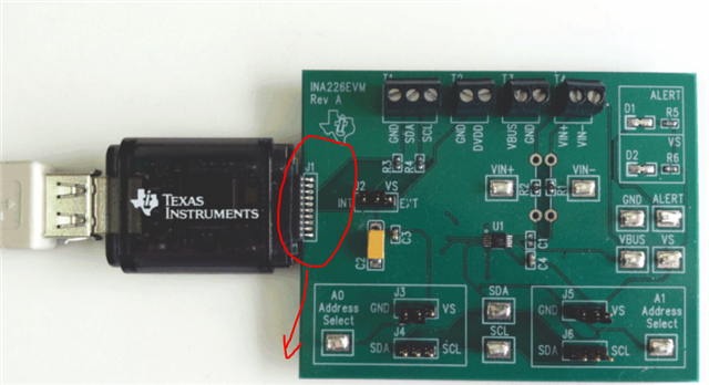
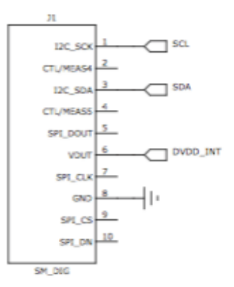
    Just wanted to include another comment. The customer may be able to use the SM-USB-DIG (which is used with the Rev A EVM/GUI) similarly to how I described above. They can use the Rev A GUI with SM-USB-DIG, then connect the SM-USB-DIG to the appropriate I2C lines on the customers hardware (you can determine the pins using the Rev A EVM user guide). 

    The Rev B GUI/EVM is a bit more user-friendly, so I would recommend the solution I mentioned in the previous post. However, if you want to find a solution with the Rev A GUI and SM-USB-DIG, this is another option. 

    Thanks,

    Cierra

  • Hi Cierra,

    Actually the hardware device we have is SM-USB-DIG only, have you communicate with devices on customer 's board with the second method, is there any reference guide we can access to finish these?

    BR

    Fanbin

  • Hi Fanbin,

    I have not done this method with a customer's board and we do not have a guide on how to do this with the hardware other than the TI EVM.

    The only difference between using the EVM/guide as intended is that you are physically hooking up the wires to the customer's I2C lines instead. The GUI should work the same. You should connect from the SM-USB-DIG pins (use the J1 pinout guide) directly to the corresponding lines on the customer's board. Make sure the customer's MCU does not communicate on these lines during this process, which will cause interference. Then use the GUI as you would with a EVM.

    Cierra