Hi,
I am going to design 0-20mA and 4-20mA both current in Single XTR111... can u help me for design... this is new to me....input is coming from DAC 5V....
This thread has been locked.
If you have a related question, please click the "Ask a related question" button in the top right corner. The newly created question will be automatically linked to this question.
Hi,
I am going to design 0-20mA and 4-20mA both current in Single XTR111... can u help me for design... this is new to me....input is coming from DAC 5V....
Hello,
The information below will help you design the circuit you're interested in.
Copy the schematic in Figure 46 of the datasheet (shown below) to configure the XTR111 to create a 0-20mA span using the XTR111 from a 0-5V DAC signal.

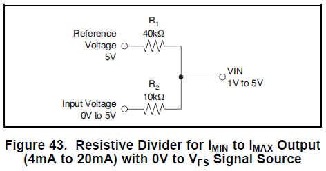
To configure the XTR111 circuit in Figure 46 to output a 4-20mA signal, the internal regulator should be configured for +5V and the resistor network shown in Figure 43 needs to be implemented on the input to the XTR111.

Then to be able to control whether the output will be 0-20mA or 4-20mA, a switch needs to be inserted that disconnects the 40kOhm resistor from the +5V regulator output signal. This is shown in the circuit below.
If you're not comfortable leaving the 40kOhm resistor floating in the 0-20mA mode, then the SPST switch can be changed to a SPDT switch that connects the 40kOhm resistor either to the +5V regulator output, or back to the input.

With the switch open, the output is 0-20mA. When the switch is closed, the output is 4-20mA.
Best Regards,
Collin Wells
Precision Linear