Other Parts Discussed in Thread: OPA837
Hello Team,
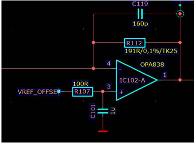
my customer has designed the following TIA and observe an non linear temp. drift issue:

The supply voltage of the OPA838 is 0V and 3.3V, the VREF_OFFSET is 1.45V, so that we can use the TIA in both "directions" around the reference voltage despite unipolar voltage supply.
The requirements for the OPA838 are very high in that its amplitude linearity should be very constant, both over input current and temperature.
Unfortunately, we see in measurements that non-linearities show up here. We modulate a current source with the input signal with non-linear characteristic as input signal (X-axis of the following graph) and record the output signal of the TIA (Y-axis of the graph) at different temperatures. Here it can be seen that the curves intersect at an output amplitude of about 300mV at the two measurement temperatures.
1. could this be due to a temperature-dependent amplification?
2. possibly in combination with the small and large signal behavior of the OPA838?
3. is there a recommendation which OPAMP is even better here?
Regarding the table: the amplitude is formed as difference of "High - Min", the last column shows then the difference of the amplitudes at different temperatures. Here you can see in the range of 0.2 - 0.9 (input current source) a maximum difference of about 4.8mV. An always equal difference would not be a problem, the "intersection" of these curves (nonlinear effect) is what gives us problems.
|
Input current source [V] |
50°C |
25°C |
|||||
|
High [V] |
Min [V] |
Amplitude [V] |
High [V] |
Min [V] |
Amplitude [V] |
Difference (25°C - 50°C)[V] |
|
|
0,20 |
1,4308 |
1,4282 |
0,0026 |
1,4338 |
1,4312 |
0,0026 |
-2,2204E-16 |
|
0,30 |
1,4308 |
1,4263 |
0,0045 |
1,4338 |
1,4296 |
0,0042 |
-0,0003 |
|
0,40 |
1,4307 |
1,4224 |
0,0083 |
1,4338 |
1,4261 |
0,0077 |
-0,0006 |
|
0,50 |
1,4306 |
1,4112 |
0,0194 |
1,4346 |
1,4155 |
0,0191 |
-0,0003 |
|
0,60 |
1,4315 |
1,3763 |
0,0552 |
1,4346 |
1,3837 |
0,0509 |
-0,0043 |
|
0,70 |
1,4337 |
1,3209 |
0,1128 |
1,4357 |
1,3277 |
0,108 |
-0,0048 |
|
0,80 |
1,4337 |
1,2524 |
0,1813 |
1,4357 |
1,2563 |
0,1794 |
-0,0019 |
|
0,90 |
1,4337 |
1,1801 |
0,2536 |
1,4257 |
1,1808 |
0,2449 |
-0,0087 |
|
1,00 |
1,4337 |
1,1038 |
0,3299 |
1,4392 |
1,1038 |
0,3354 |
0,0055 |
|
1,10 |
1,4353 |
1,0271 |
0,4082 |
1,4392 |
1,0233 |
0,4159 |
0,0077 |
|
1,20 |
1,4353 |
0,948 |
0,4873 |
1,4392 |
0,94 |
0,4992 |
0,0119 |
|
1,30 |
1,4353 |
0,833 |
0,6023 |
1,4392 |
0,826 |
0,6132 |
0,0109 |

I hope you can help!
Thanks
Jan

