This thread has been locked.

If you have a related question, please click the "Ask a related question" button in the top right corner. The newly created question will be automatically linked to this question.

INA592: 4-20mA current source

Part Number: INA592
Other Parts Discussed in Thread: DAC8760, XTR111, DAC8750, , XTR305, XTR300, DAC8771, DAC8775

Hello Team,
We plan to design a 4-20mA current source as a sensor output
1). Can I use a Howland current pump as described in the application note Analysis of Improved Howland Current Pump Configurations?
2). Or do we need to use specified ICs like XTR111AIDGQR?
We need a resolution of 0.3 μA and an accuracy of ±2.5 μA.
The load regulation will be ±0.02% rdg (0 to 500Ω).
0.15uA accuracy
3). Can I use DAC like DAC8760 for this application?

Looking forward to your response


  • Hi Shibin,

    0-10V is often gained by the help of a 500R burden resistor in combination with a 0...20mA current output. This soultion is not optimal because of the rather high source impedance due to the 500R burden resistance. But this solution is often used in industry, especially if the cable is not all too long.

    To be able to go all the way down to 0V at the output in a 0...20mA application, the Howland current pump needs a bipolar supply voltage. The output stage of XTR111, on the other hand, works totally different and is free from this restriction. So, if you only have a positive supply voltage, the XTR111 may be the better choice. Another disadvantage of the Howland currrent pump is that it is not an easy task to stabilize the Howland current pump for differing complex loads. This is another reason why it is not widely used in 0/4...20mA applications.

    Another way is to use the DAC8750 or DAC8760.

    Kai

  • HI Shibin,

    As Kai has mentioned, on the current transmitter application, the main issue with the Howland Current source configuration is that could be sensitive to capacitive/inductive load and will likely become unstable while driving a long cable.  There are possible circuit configurations as the one shown on the INA592 on Figure 9-9 using the NPN transistor that could be used on a 4-20mA current transmitter application, but these are limited to applications with low cables or relative low capacitance load of a few 10's of nanoFarads.

    However, in general, if the application is primarily concerned about DC precision/accuracy, with limited bandwidth to a few kHz, the XTR111, XTR300, XTR305 are good options providing a robust solution with excellent DC accuracy.  The DAC8760 is also popular solution, these are supported by the DAC team.

    The XTR111 is probably is a good option for a 3-wire current transmitter 4-20mA, meeting your accuracy requirement while working with a unipolar supply.

    The XTR300 and XTR305 are another option, these can be configured as current output or voltage output mode, supporting up to 24mA output linear operation, or voltage output configuration, will support the 0-10V transmitter output.  However the XTR300 requires a bipolar supply with (V-) <= -5V or more negative.

    Attached couple of reference design featuring the XTR300, XTR111, DAC solutions that may be of interest:

    3-wire transmitter reference designs: 

    Thank you and Regards,

    Luis

  • Hello Kai,
    Thank you for your reply.
    DAC8750 or DAC8760 is not available in Mouser or Digikey or in the TI store.
    We have +/-15V available in the board, so using bipolar voltages for Howland won't be difficult

    What will be the accuracy if we are using XTR111?
    We need a resolution of 0.3 μA and an accuracy of ±2.5 μA.
    The load regulation will be ±0.02% rdg (0 to 500Ω).

  • Hello Luis,
    Thank you for your reply.
    What is the accuracy if we are using circuit configurations such as the one shown on the INA592 in Figure 9-9 using the NPN transistor that could be used on a 4-20mA current transmitter application?
    We need a resolution of 0.3 μA and an accuracy of ±2.5 μA.
    The load regulation will be ±0.02% rdg (0 to 500Ω).
    Is the circuit capable of driving long cables considering the inductive and capacitive load in the cable?

    XTR300 and XTR305 are not avialbe on Mouser or Digikey or in the TI store.


  • Hello Shirbin,

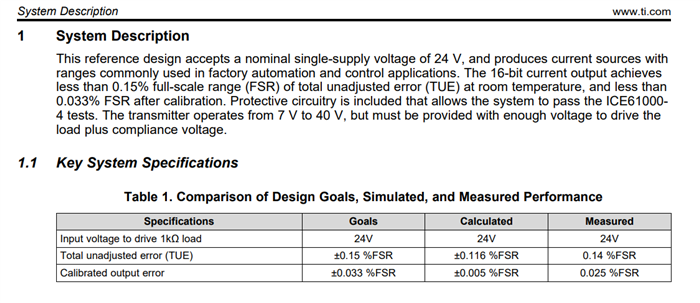
    Regarding the overall XTR111 circuit accuracy, the errors will be a heavy function of the DAC or the circuit generating the input voltage signal of the XTR111, the reference of the DAC; as well as the XTR111 gain error, offset, linearity; and the RSET resistor accuracy/tolerance. If you review the XTR111 reference design TIDA-01536 , the reference design provides a design example with an estimate of the Iout accuracy.

    The User guide offers of the reference design an estimate of the total unadjusted error (TUE) estimated at ±0.116 % FSR. After performing calibration, the design offers an estimated ±0.005% FSR calibrated error, and meausured, ±0.025%,

    Please review section 2.2.1  Calculated IOUT Accuracy on page 3 of the design guide.

    Design guide — TIDA-01536

    Regarding the INA592 on Figure 9-9, we do not offer a reference design, and the errors will be a heavy function of the resistor tolerance, as well as errors in the input voltage source.  As we have discussed, the XTR111 (and/or XTR300/XTR305 when available) are optimal for 4-20mA applications offering a robust solution.

    Thank you,

    Luis

  • Hello Luis,
    Thank you for your reply.
    I understood the best method to generate a 4 - 20mA is to use XTR111 (and/or XTR300/XTR305 when available).
    But none of them is available from any of the trusted vendors.
    So we have to search for alternate options.
    Can we use INA592 to generate a 4 - 20mA current as instructed by the figure Figure 9-9 in the datasheet?
    The DAC we are planning to use is a 16-bit DAC (DAC8574IPW) and we are planning to use a 0.1% tolerance resistor or better.
    WIll the inductive and capacitive parasitic load on the cable effect the stability/ performance of the system?

    Looking for your reply.

  • Hi Shibin,

    these circuits look good on paper but may not be so good looking in practise. The circuit shown in figure 9-9 of datasheet of INA592 suffers from the fact that the -input of internal OPAmp is not accessible and that you cannot add a suited phase lead capacitance in order to stabilize the current pump from complex loads (cable capacitance !). So, this circuit may perfectly work without any complex load and with short connections at the output but need not necessarily to work properly with a long, "real world" cable.

    Also keep in mind that for a proper protection of the output against ESD, Surge and Burst and for a proper EMI filtering usually a filtering cap (10...100nF) in parallel with a TVS is mounted from the output to signal ground. So, you have a complex load even already without any cable. And when connecting a cable of varrying length, the capacitive load the current pump sees is also varrying. So, for a proper and stable operation you would need to compensate the current pump by the help of a very specific phase lead capacitance, but which you cannot connect to the INA592, because the -input of OPAmp is not accessible.

    Kai

  • HI Shibin,

    The INA592 is intended to be used as a difference amplifier, and it is not a device developed to be a industrial 4-20mA current transmitter. Hence, there are no reference designs for the INA592 as a 4-20mA current transmitter.  The circuit suggested on Figure 9-9 of the datasheet can only reliably drive capacitive loads of a few 10's of nanoFarads while remaining stable, therefore, it is limited to applications driving relatively short cables or relative low capacitance load.  Kai has explained above that the inverting terminals of the internal amplifier is not  directly bonded out, making compensation difficult.

    The XTR111, XTR300, XTR305 and DAC8760 and the reference designs mention above are robust solutions for the 4-20mA current transmitter applications.  Some of these devices appear to have inventory available on TI.com.

    Thank you and Regards,

    Luis