This thread has been locked.

If you have a related question, please click the "Ask a related question" button in the top right corner. The newly created question will be automatically linked to this question.

OPA2277: condition for the phase reverse to happen

Part Number: OPA2277
Other Parts Discussed in Thread: OPA277, TINA-TI

Hi team,

My customer is using OPA2277UA/2K5 and has confirmed below phenomenon. It seems that there is a dip in the output due to the reverse phase.

Could you kindly answer to the questions below?
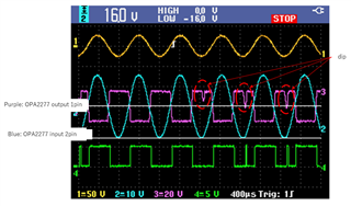
It seems that the above phenomenon is caused by the reversed phase of the op amp.
They have guessed that the conditions that the reverse phase happens are:


①when VIN is greater than or equal to the specified value for Vin (VCM: VCC +/- 2)
②when output is saturating


Is it the "AND condition of ① ② (phase reversal occurs with both)?
Or is it an "OR condition" of ① ② (phase reversal occurs with either case)?

Could you tell us when this happens?

Regrds,

Ohashi

  • My customer wants to know what specific overvoltage will the reverse phase issue occurs.

    Regards,

    Ohashi

  • Hi Ryoma,

    What is the supply voltage? Can you show a schematic?

    Kai

  • Hello Ohashi,

    Phase reversal occurs when the input common-mode voltage exceeds the linear operating region of the amplifier input (option ). In the case of the OPA2277, VCM should stay within 2V from the supply rails as you stated. When the input common-mode range is violated, the input transistors are not biased properly causing non-linear operation.

    As far as when this occurs – we do not spec the part outside of the VCM range so we cannot state exactly where phase inversion starts to occur. To maintain linear operation, it is important to stay within the input common-mode range.

    The slides below go further in depth if you are interested:

    op_amp_phase_inversion.ppt

    If you have additional questions, please let me know and please include the schematic.

    Best regards,

    Brittany Hertneky

  • Hi Brittany,

    Thanks for your support.

    I have an additional questions from the customer.

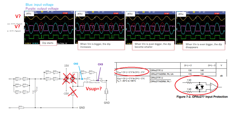
    The customer has measured the wave form with several input voltage.

    When they increased the input voltage, they confirmed a unique phenomenon.

    The customer wants to know why this happens.

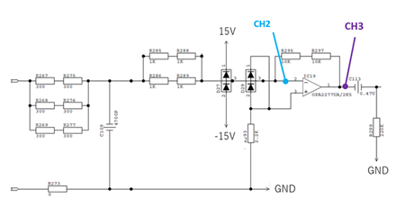
    Here is the schematic.

    I’m guessing that when the input voltage increases, the slew rate of the dip (rising and falling) gets bigger. And when the slew rate of the dip exceeds the spec, it disappears. Is this correct?

    Regards,

    Ohashi

  • Hi Ohashi,

    it may be that the OPAmp is damaged. I would check the performance with a fresh OPA2277.

    Then, I would think about removing D27, because D27 makes that a rather high current is injected into the supply lines when the input voltage exceeds the supply voltage (+/-15V?) of OPA2277. If the voltage regulators cannot absorb this reverse current, the supply voltage can rise without being limited and by this eventually damage the OPAmp. And more issues may occur during power-down of OPAmp while an input signal is present.

    Removing D27 does not harm, because you still have D29. But to make it properly work, I would reduce R293 to zero Ohm.

    And I would think about using a voltage divider at the input and by this to prevent the output of OPAmp from clipping.

    Kai

  • Hi Kai,

    Thanks for your recommendation.

    Any update on the root cause of the dip disappearing?

    Regards,

    Ohashi

  • Hi Ohashi,

    have you checked the performance with a fresh OPA2277?

    Kai

  • Ohashi,

    OPA277 itself does not suffer from phase inversion. However, since there are input protection diodes inside OPA277 (see below), please ask your customer to remove all of the external diodes shown in front of the op amp.

    If the issue persists, please specify the supply voltage (Vsup) used by the customer and label the magnitude of the input/output waveforms so we can make the judgement about the cause of the output phase reversal they see.

  • Hi Marek,

    Thanks for your support!

    I have shown to the customer that D27/D29/R293 is not needed. The customer is OK with it.

    But for the root cause of the phemonenon, the customer thinks that it is not due to the reverse current since the customer is not putting a such high current on the input. My customer thinks that the device is not damaged.

    Here's the voltage info:

          Input:Vin: 52Vp-p  (+26V-26V)

                             IC19-2(CH2): 32Vp-p (+16V-16V)

          Output: IC19-1(CH3): 29Vpp (+14.5V -14.5V)

    Do you have any other idea for the root cause of the phenomenon?

    Regards,

    Ohahsi

  • Ohashi,

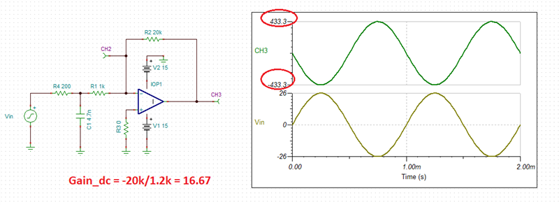
    What your customer sees makes perfect sense for overdriven input signal and may be simulated - see below. 

    Since the gain of the circuit is G=-16.67, applying +/-26V input signal would require the output to go to Vout=16.67*(+/-26V) =+/-433.3V, which obviously is not possible on +/-15V supply - see below simulation using ideal op amp.

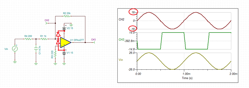
    Thus, the CH2 gets clampped around +/-16V (see below) by the ESD protection diodes between the input and eacg supply rails while the output (CH3) gets pushed against its rails around +/-14.5V - these are very close to what the customer sees.  

    The phase inversion is not modeled but may occur for the input common-mode voltages (Vcm) greater than 0.7V beyond the rails - see be,ow.

    Below I have attached Tina-TI circuit for your customer convenience.

    Ohashi OPA277.TSC

  • Hi Marek,

    Thanks for your detailed explaination.

    The customer understood that the input is out of the common mode range in this case.

    The question from the customer is: What is the root cause of the phenomenon that the reverse phase disappears when the input voltage gets even higher?

    Regards,

    Ohashi

  • Hi Ryoma,

    The question from the customer is: What is the root cause of the phenomenon that the reverse phase disappears when the input voltage gets even higher?

    Because several different effects partially offset each other. But since the input signal goes beyond the supply voltages and even violates the absolute maximum ratings this becomes a more and more fruitless and purely academic discussion. And since you are walking into the no man's land for which no specifications are given in the datasheet, you must not expect that you are free from phase reversal any longer.

    There are three regions of operation:

    1. The input signal stays 2V away from the supply rails. This is the recommended and specified common mode input voltage range. Everything is fine.

    2. You are outside this common mode input voltage range, but still inside the supply voltages: The circuit no longer works linearily, but no phase reversal will occur.

    3. You not only leave the common mode input voltage range, but also exceed the supply voltages: The circuit no longer works linearily and the absence of phase reversal can no longer be guaranteed. You start to risk damage and even total destruction of OPAmp. Never enter this no man's land during normal operation, neither repeatedly or periodically nor for conitnuous periods.

    One way to achieve this is to remove D27, to keep D29 and to reduce R293 to zero Ohm, as already mentioned above. Section 7.3.4 of datasheet explains why the OPA2277 does not need such an input bias cancelling resistor any longer.

    Kai

  • The phase reversal disapears because under gross violation of the Vcm the input terminals are pulled far apart and the op amp becomes a comparator - this means that the output slams againt its rail.

    I'd like to add here one more point to Kai's litany of reasons why customer should NOT do what they do:

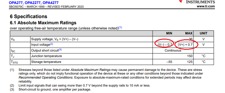
    4. You not just exceed the supply voltage by a small voltage BUT exceed it beyond the Absolute Maximum Rated voltage of 0.7V where you may fully expect damaging the part unless the input current is limited to 10mA or less.