This thread has been locked.

If you have a related question, please click the "Ask a related question" button in the top right corner. The newly created question will be automatically linked to this question.

TLV9352: Design Advise for Op-Amp Application

Part Number: TLV9351
Other Parts Discussed in Thread: TL081

Hi,

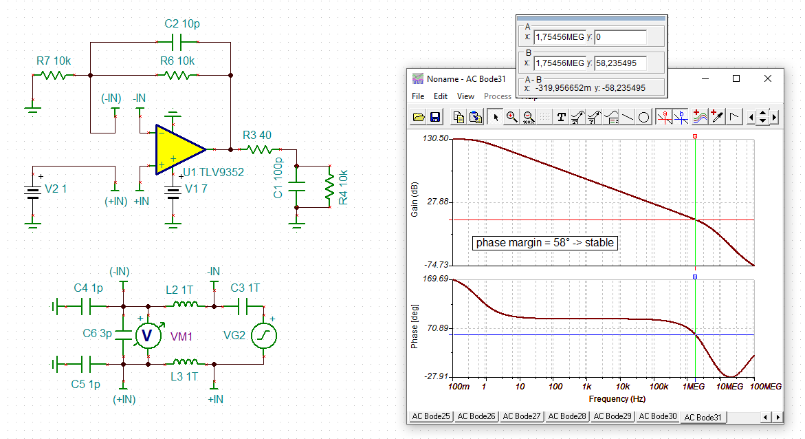
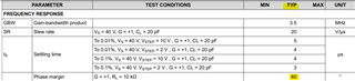
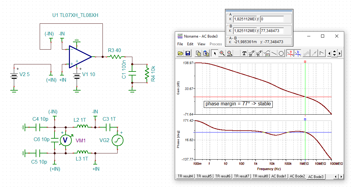
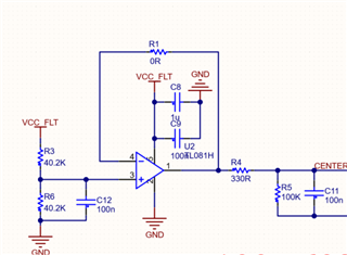
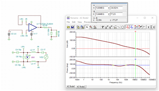
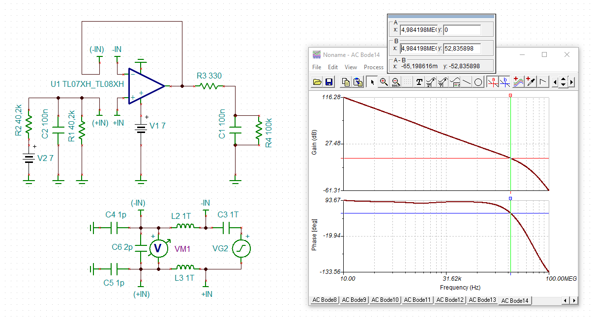
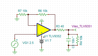
I am using TLV9351 to drive capacitive load with isolation resistor. The circuit schematic is attached.

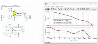
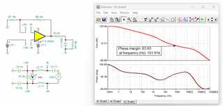
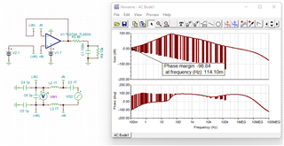
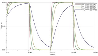
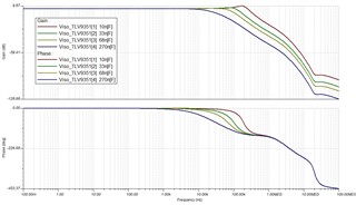
The simulation results are attached.

Cload Compensation_TLV9351_last.TSC

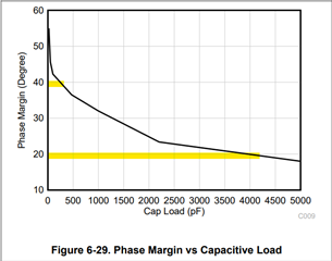
1.What is the maximum and minimum capacity can I use?

2. What will happen if I drive TLV9351 with 0-7V input voltage when the supply voltage is 7V? Can I drive it like that?

  • Hi Egemen,

    I would run a phase stability analysis:

    egemen_tlv9352.TSC

    Note the phase lead capacitance C2 that I have added to enhance the stability.

    You also may want to watch these TI's training videos on stability:

    https://training.ti.com/node/1138805

    Referring to your second question: For best performance I would add an input voltage divider, to restrict the input voltage to the "better" input voltage range (0V to Vs - 2V) and to prevent a clipping of output stage.

    Kai

  • Hi Kai thanks for the reply,

    According to the simulation the phase slightly increases like 1-2 degrees

    Currently there is no space for 10pF in the PCB so the final circuit shall be like this

    In the final circuit, capacitive load shall be betwwen 100-220nF and simulation results are attached.

    1. Is this circuit stable at these capacitances?

    2. Increasing the capacitance also increases the phase margin is that correct?

    3. Should the minimum phase angle be 45 degrees?

  • Hello Egemen, 

    Here is the link to the training series Kai provided earlier, https://www.ti.com/video/series/ti-precision-labs-op-amps.html
    I don't believe Kai's link worked earlier as TI has changed the video landing page. 

    A design's phase margin is a good tell of how stable the circuit is, traditionally you would like to ensure at least 40 degrees of phase margin in order to account for the 20 degrees of PM in lot/fab variance of a device. 

    The TLV935x can drive up to 3500pF (3.5nF) without additional circuitry to improve stability, according to Figure 6-29 in the datasheet. 

    There are ways of improving stability, like an RISO (R3) or the addition of a feedback cap (like Kai's suggestion of C2). 

    Therefore to answer your questions, 

    In the final circuit, capacitive load shall be betwwen 100-220nF and simulation results are attached.

    1. Is this circuit stable at these capacitances?

    2. Increasing the capacitance also increases the phase margin is that correct?

    3. Should the minimum phase angle be 45 degrees?

    1. The circuit appears to be stable since 74 & 83 >> 40 degrees of phase margin. 

    2. This is incorrect, usually increasing capacitance lower your phase margin. The choice of RISO and RLoad change your phase margin. I suggest looking at the trainings to adequately size your compensation circuitry. Additionally, what simulation shows and the device receive in real life has variance (as PM is a typical spec). Therefore I recommend to prototype your circuit to ensure the RISO is the correct value. 

    3. At least 40 degrees of phase margin is recommended. 

    All the best,
    Carolina 

  • Hi,

    I also designed with unity gain opamp(TL08XX) circuit to drive capacitive load but the AC bode output is weird

    What is wrong in this design?

    4035.Cload TL08XX.TSC

  • Hi Egemen,

    the TL081 is no rail-to-rail OPAmp and you violate the common mode input voltage range. Also, the supply voltage is too low and you have set incorrect input capacitances.

    After correcting these mistakes you will get this:

    Kai

  • Hi thanks for the reply again

    The final circuit will be like this


    the isolation resistor may be selected 330R or 40R simulation result is attached

    so is it stable right?

  • Hi Egemen,

    more stable with 40R than with 330R:

    Kai