This thread has been locked.

If you have a related question, please click the "Ask a related question" button in the top right corner. The newly created question will be automatically linked to this question.

LM358: constant current source for LED

Part Number: LM358
Other Parts Discussed in Thread: LMV2011,

Hello,

I designed current source circuit for LED.

I didn't understand how it works.

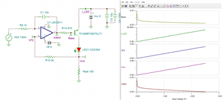
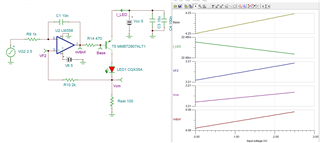
I changed only the OP AMP in the same circuit, but the simulation operation does not work with the LM358.

Is something wrong with this circuit?

Is it better to drive LEDs with NPN than PNP?

1. LMV2011
2. LM358
Please help me.

  • The LM358 does not have rail-to-rail inputs or outputs. The input voltage in this application might work (if you do not reduce the temperature), but the output cannot go as high as would be required.

    The LM358's output is able to go near the negative rail, so an NPN indeed would work better. (Also, the base voltage would include the voltage drop over Rset.) But in general, you should select an opamp that has input and output voltage ranges that support your application.

  • Hi Rona,

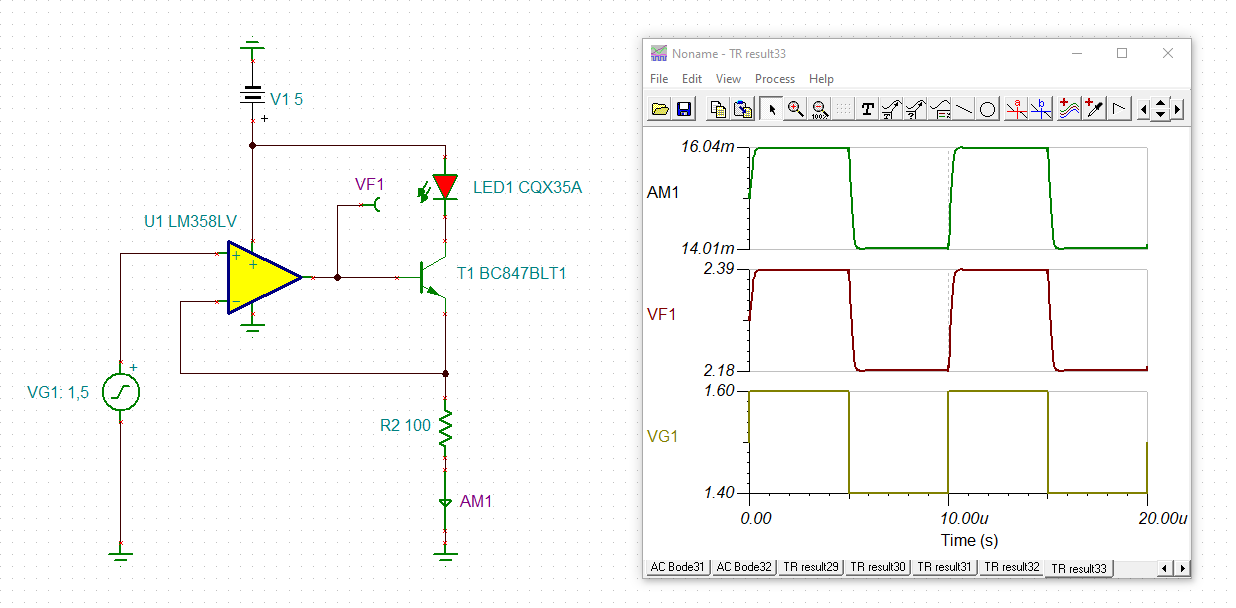
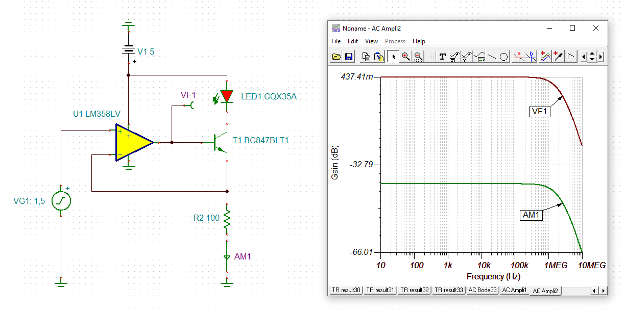
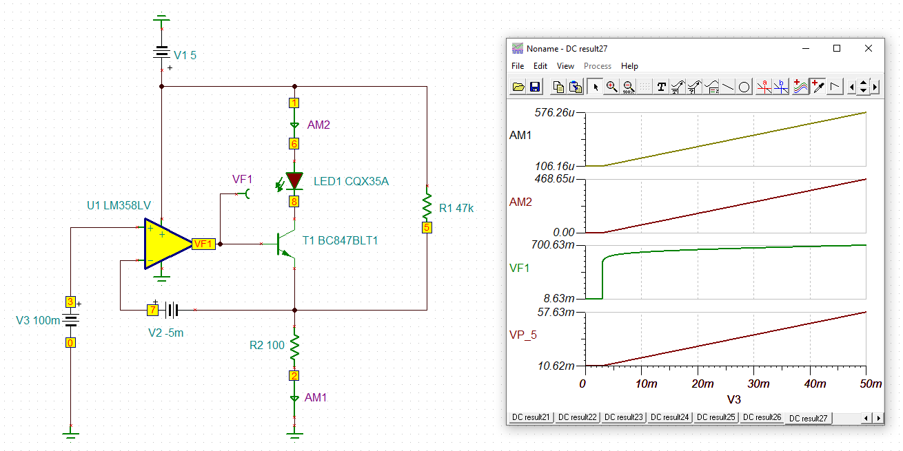
    I would give the LM358LV in combination with a small signal NPN a try. This OPAmp seems to be optimally suited for this circuit and doesn't seem to need any phase lead compensation. There isn't even the least ringing in the step response and there's no ripple in the frequency response either:

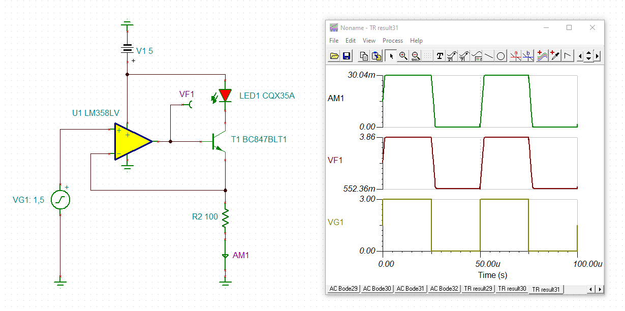
    Even the large signal step response looks good:

    rona_lm358lv_1.TSC

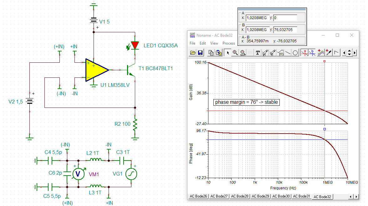
    And the phase stability analysis shows a perfect phase margin 76°:

    rona_lm358lv.TSC

    Kai

  • Thanks for the reply.
    I actually made it according to the circuit you replied to me and checked it.
    Even if 0 is input to the OP AMP input terminal, the LED lights up.
    Because the OP AMP input stage cannot be really 0V, it is about 10mV. At this time, the current flowing through the LED was about 80uA, but the LED was visible to the naked eye. Can't I make the LED completely off with this constant current circuit?

  • Rona,

    It's 10mV minimum because the sum of minimum input voltage (from your source) and op amp input offset error.

    You can add a DC offset to get a zero current. Add a pull up resistor from IN- to 5V supply that creates at least 10mV on R2.

    This give give a zero current "range" ; it also reduces current for all input voltages. It adds a DC offset to your transfer function. IOUT = (VIN-OFFSET) / R2 , but IOUT is never negative.

  • Kai