This thread has been locked.

If you have a related question, please click the "Ask a related question" button in the top right corner. The newly created question will be automatically linked to this question.

TLV1704: Output logic of comparator

Part Number: TLV1704
Other Parts Discussed in Thread: TLV1701,

Hello,

I am getting only 3.3 VDC at the output of comparator with respect to different inverting terminal voltage. See below schematic:
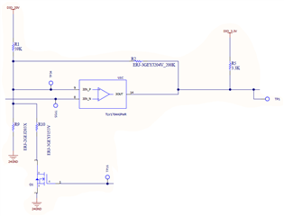
What is the role of pull up resistance at the output of comparator ?

Thanks,

Kiranjit 

  • Hello Kiranjit ,

    The TLV1701 is a "Open Collector" output. The output can only sink current, like a switch with contacts to ground.

    When the comparator output is supposed to be "low", the output transistor conducts and "shorts" the bottom of the pull-up resistor to GND. This creates the "low" (0V) output.

    When the output is supposed to be "high", the output transistor is off and not conducting. Since no current is flowing through the pull-up resistor, the output is "high" as no voltage is dropped across the resistor and the output is "pulled-up" to 3.3V.

    What are the values of R9 and R10? What is the gate voltage of the MOSFET?

    For the output to go "low", the negative input must be at a higher potential than the positive input.

  • Hi Paul,

    Thanks for your response.

    What are the values of R9 and R10? What is the gate voltage of the MOSFET?

    >> R9 : 20 K and R10 : 15K 

    >> Gate voltage is 3.3 VDC for ON condition 

    Output is not changing from 3.3 VDC.

    Is it an input biasing issue? or Comparator is not functionating properly ?

    Thanks,

    Kiranjit 

  • Hello Kranjit,

    What are the voltages on the inputs? Measured *at* the input pins (TP34 and TP35).

    What is the supply voltage for the comparator?

    A comparator is a simple device. The output will go in the direction of whichever input is at the higher voltage. If the negative input is higher than the positive input, then the output will be low. If the positive input is higher than the negative input, then the output will be high. Measure the actual voltages on the pins and you should be able to determine the output state.

  • Hi Paul,

    What are the voltages on the inputs? Measured *at* the input pins (TP34 and TP35).

    >> TP34 : 5.0 VDC and TP35 : 19 VDC 

    What is the supply voltage for the comparator?

    >> 20 VDC


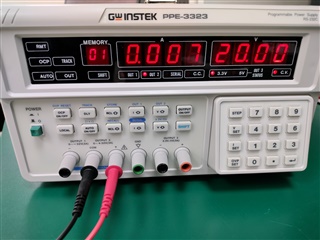
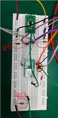
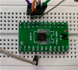
    Only middle one PCB adapter board being used without mosfet.

    Yellow wire : +20VDC 

    Red wire : Ground 

    Still, Output is not changing from 3.3 VDC.

    Please share your feedbacks on it.

    Thanks,

    Kiranjit 

  • Hello Kiranjit ,

    If the Positive input is 5V, and the negative input is 19V, then the output should be low.

    I see you are using a protoboard. I have had issues with some of the adapter boards having too short pins and not making good contact with the socket.

    Measure the voltage *at* the input pin (or at least the numbered pins along the edge of the adapter). Make sure the voltages you expect are correct on the adapter board.

  • Hi Paul,

    Thanks for your response.

    This issue has been resolved. 

    I just changed input and output terminal from 5, 4 & 2 to 7, 6 & 1. 

    Getting output as per expected calculation.

    Can you please share possible root cause for this issue? 

    Thanks,

    Kiranjit  

  • Hello Kranjit,

    Either there is a bad connection on the board, or, that channel was damaged at some point. You can try replacing the TLV1704 with a new one..

    Glad you got it working.