Other Parts Discussed in Thread: RCV420
Hi ,
I am trying to measure
min current - 4mA
max current - 20mA
four wire 4-20 current loop
Vcm-12V
Vs=3.3V.
The part I would like to use is INA350 Just would like to know if it is OK.
Thank you
This thread has been locked.
If you have a related question, please click the "Ask a related question" button in the top right corner. The newly created question will be automatically linked to this question.
Hi Forrest,
Welcome to E2E! :)
Could you clarify what the intended input signal is and why the Vcm range is 12V?
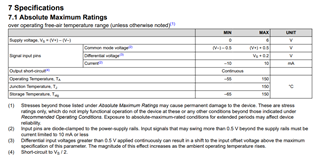
The INA350 Vcm range Abs max can only go 0.5V beyond the supply voltage rails so 12V would damage the part.
Please let me know if you have any questions.
Thank you!
Best Regards,
Ashley
Hello Ashley,
Thank you very much.
Sorry, it's my fault. The Vm is 5V instead of 12V.
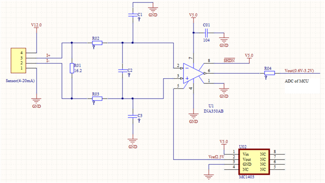
We are trying to develop a receiver that allows reading 4 – 20mA current from oxgen sensor and converting it to voltage to be processed by the ADC of a Microcontroller. I am attaching the schematic diagram, I need to know if it is correct or if you could recommend any parts for our application.
I appreciate your help.
Sincerely,
Forrest
Hi Forrest,
Thank you for the additional information! I think there was a bit of a misunderstand in terminology when I asked about Vcm. I meant to ask about common-mode voltage of the INA device (the average voltage across IN+ and IN-). This was why I mentioned the abs max table. Do you know this value going into the INA?
Do you have the passive values determined for the input stage filtering? Do you know which frequencies you are trying to filter out or keep?
Overall, I do not see any major issues with the schematic and using the INA in this application but do want to verify some things with the input stage before confirming.
Please let me know if you have any questions.
Thank you!
Best Regards,
Ashley
Hi Ashley,
Thank you for taking the time to understand our query.
question: the common-mode voltage of the INA device
answer: the commom-mode voltage of the input signal is 0v
question: the input signal frequencies you are trying to filter out or keep
answer: I'm not sure about the frequencies, I will get this information from the supplier of the sensor
the modified shematic as follow:
I found another method in this forum as follow
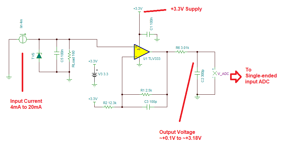
Please let me know the most optimal way of doing that?
Sincerely,
Forrest
Hi Forrest,
and you can do it directly, without any OPAmp, as shown in this thread:
Kai
Hi Kai,
Thank you for answer and direction.
There are several methods as above including which you told me. I want to know which is the most optimal way .
Best,
Forrest
Hi Forrest,
there's no simple answer:
If you put more than one burden resistor in series, then you may need an "instrumentation amplifier" or at least a "diferential amplifier" design to suppress the common mode input voltages caused by the voltage drops across the other burden resistor(s). Figure 10 of datasheet of RCV420 shows an example. Or if for any other reason a common mode input voltage is superimposed to the regular voltage drop across the burden resistor, you may need such a design.
If the burden resistor is allowed to be referenced to signal ground, on the other hand, then a simpler approach can be used. This can either be a direct connection, if no additional gain has to be provided, as shown by me in the linked thread above. Or, if the voltage drop across the burden resistor is too small, because the burden resistor has to be kept small for some reason, then an additional OPAmp may be necessary.
And if you need to convert the 4...20mV signal into 0...5V, because you cannot let a µC perform this conversion for you, then an even more complex circuit is necessay, like this for example:
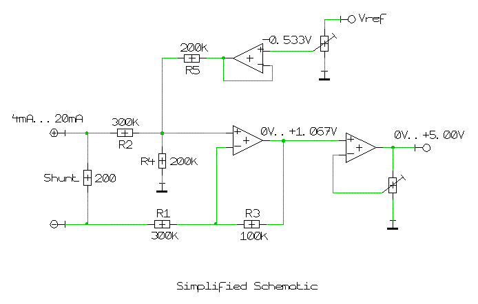
Or again the RCV420 may be used.
If in this case the OPAmp cannot go all the way down to 0V at its output, you may need an additional negative supply voltage.
Kai
Hi Kai,
Thanks a lot for your info, very helpful!
The burden resistor in my circuit is allowed to be referenced to signal ground, so I will connect the burden resistor directly.
Best,
Forrest