This thread has been locked.

If you have a related question, please click the "Ask a related question" button in the top right corner. The newly created question will be automatically linked to this question.

XTR111: Current limit

Part Number: XTR111

Hello team,

I received questions from the customer.

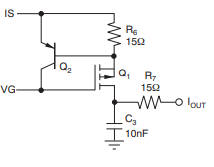
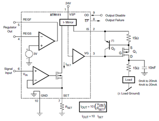
Adding the recommended external current-limiting circuit shown in the datasheet, as shown in the following figure, will prevent a current flow of more than 50 mA even if the load is short-circuited?
Regards,

Masa

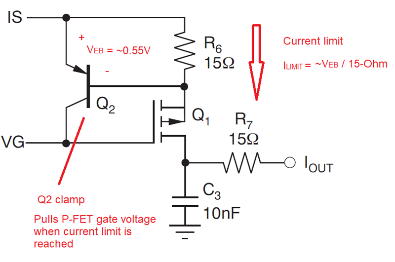
  • When the voltage drop over the resistor reaches VBE, Q2 switches on and pulls the gate up.

    The current limit is VBE / 15 Ω. The transistor's VBE has large temperature and manufacturing variations.

  • HI Masakazu-san,

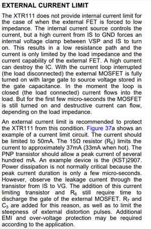
    The XTR111 datasheet "External Current Limit" section on page 13 explains in good detail this circuit.  The 15-Ohm resistor (R6) limits the current to approximately ~35mA, that is, one diode drop, VBE / 15-Ohm =~0.55V / 15-ohm. The PNP transistor Q2 forms a clamp keeping pulling the PFET gate up when the voltage across the 15-ohm resistor is equal to a VBE drop. The current limit is primarily a function of the VBE diode drop. This circuit is required, and it is intended to protect the XTR111 from a fault condition, since the XTR111 does not incorporate a current limit function that protects from a fault.

    Without the external clamp, a fault can occur when the loop load is disconnected, turning the Q1 P-FET fully on. With the current loop open, when the load is disconnected, the external MOSFET is fully turned on with large source to gate voltage stored in the gate capacitance. The moment the loop is closed, when the load is connected again, current flows into the load. When the P-FET is still fully turned on, with the gate low, a low resistance path results and destructive current can flow, depending on the load impedance. The external current limit is required to protect/recover the XTR111 from this condition, where the clamp pulls the P-FET gate high when the high current occurs.

    Since the VBE voltage is a strong function of temperature, it is not intended as a precise current limit function.

    Please see below:

    Thank you and Regards,

    Luis

  • Hello Clemens, Luis,

    Thanks for the support.

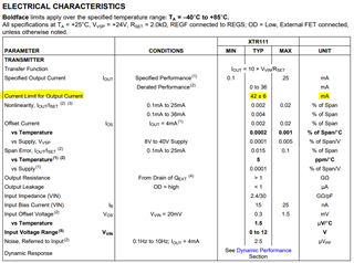
    What does the 42±6 mA listed in the datasheet mean, does it mean the current limit without the external current limit circuit?

    Regards,

    Masa

  • Hello Clemens, Luis,

    Thanks for the support.

    What does the 42±6 mA listed in the datasheet mean, does it mean the current limit without the external current limit circuit?

    Regards,

    Masa

  • HI Masakazu-san,

    The XTR111 current output performance specifications is from 0.1mA to 25mA.  The device can also support derated output current range to 0-36mA without issues. 

    The IS pin current absolute maximum rating, or the maximum current that can flow through the IS pin of the XTR111 device without causing permanent damage during a fault is 50mA (source) or 25mA (sink) as shown on page 2 of the XTR111 datasheet. 

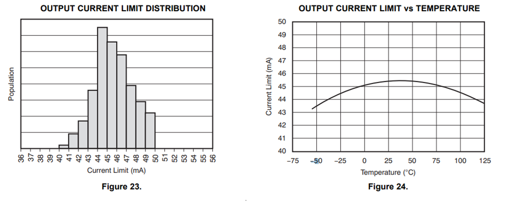
    During normal operation, with the load connected and the current loop closed, the XTR111 device offers the "Current limit for output current" function will the current to a typical 42±6mA to limit the current to less than 50mA.  Figure 23 shows the XTR111 device "Output current limit distribution" and Figure 24 shows the "Output current limit vs temperature".   

    However, as explained on page 13 of the datasheet, the XTR111 does not provide an internal current limit function to protect for the fault case where the current loop is opened, and then closed with a low impedance load while the device is enabled/powered up.  Since the gate voltage of the PFET will be set low when the current-loop is opened, the moment the current loop is closed, or the load is re-connected while the device is powered up, for a few microseconds, high current will flow through the load, since the P-FET is fully turned-on, and will provide a very low impedance path, through the FET resistance Rds ON resistance, resulting on a sudden large current transient.  Hence, the external current limit circuit is required to pullup or clamp the gate voltage when current flows through R6 during this transient.  The external current clamp needs to limit the current to 50mA or less to not exceed the absolute maximum ratings of the device.  Please review the section below.

    To answer your question, the XTR111 without the external current limit circuit, will limit the output current to 42±6mA during normal operation.  However, the internal current limit can not limit current for the fault case with the case above, hence, the external current limit circuit is required, and the external current limit needs to be set  to ~50mA or less.

    Thank you and Regards,

    Luis   

  • Hello Luis,

    Thanks to explain the details. I shared this thread with the customer.

    Regards,

    Masa