This thread has been locked.

If you have a related question, please click the "Ask a related question" button in the top right corner. The newly created question will be automatically linked to this question.

AMC1302: AMC1302 TINA waveform distortion

Part Number: AMC1302
Other Parts Discussed in Thread: AMC1203

Hi Team,

My customer is evaluating AMC1302 with Tina simulation file below, 

IL_sensor circuit_use AMC1302.TSC

there are some questions below from customer,

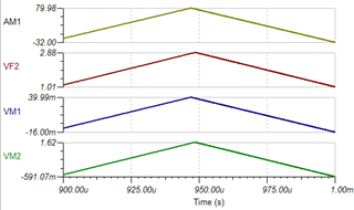
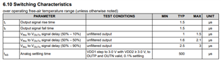
1. VM1 and VM2 are AMC1203 input and output waveform, there is some distortion with triangle waveform, is it due to AMC1302 BW limit?

2. the maximum input current is 80A with Rshunt 0.5mΩ

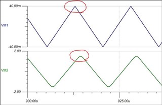
   The output voltage should around 0.5mΩ x 41 x 0.845 + 1.5 = 2.8858V, but VF2 voltage is 2.76V. is there some loss in this circuit?

3. there is 1.54us output delay, is this AMC1302 internal delay?

Thanks & Regards

Eddie Chou

  • Hi Eddie,

    1. Yes, the "distortion" or shaved peak of the triangle waveform is due to the bandwidth limitation of the isolated amplifier. Slowing the input signal frequency to 6.6kHz instead of 66kHz, you can see that the output is no longer bandwidth limited.

    2. Node to node, the input waveform does not make it to 80A, but 79.06A, which correctly equals 39.53mV at the input of the AMC1302. The AMC1302 has an internal gain of 41, which should equal a 1.62V peak on the output, but due to the bandwidth limitation as described in #1, this is limited to 1.48V. Multiplied by the gain and offset of the opamp, yields 2.75V, correct through the differential to SE stage. 

    3. Yes, that is correct.