This thread has been locked.

If you have a related question, please click the "Ask a related question" button in the top right corner. The newly created question will be automatically linked to this question.

TLV4316: Amplifier response time delay

Part Number: TLV4316
Other Parts Discussed in Thread: LM339

Hi,

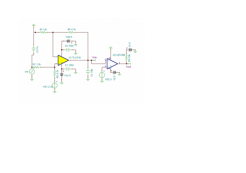
I have a differential amplifier(TLV4316) whose output is given to a comparator(LM339).

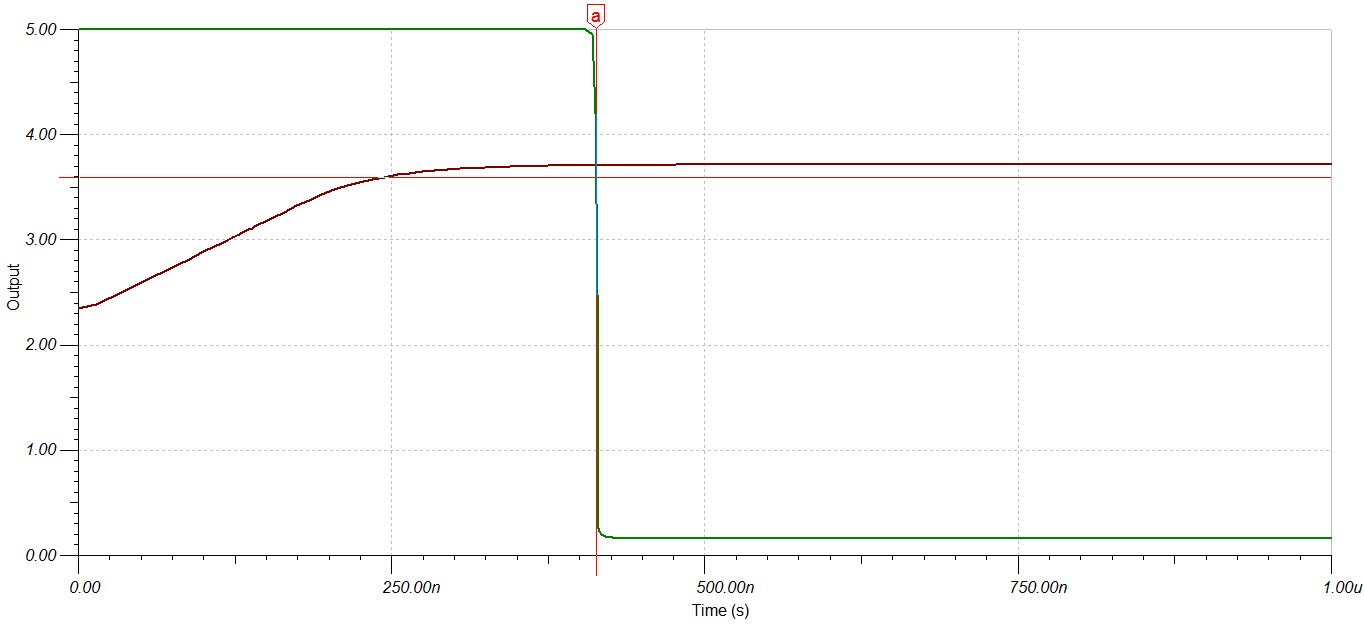
With a 10us input pulse, the simulated output falls to 0 after about 450ns.

However, actual waveform is delayed by approx 3us on the PCB with exactly the same components.

Both, simulation and actual waveforms are attached.

In the actual waveform - Yellow is the input pulse, Blue is the comparator output.

Sorry about the ringing as this was a 80A short circuit.

Please ignore comments in the actual waveform.
  • Hello Amar,

    A few factors may be in play. If the op amp starts at rail, 0V, then there will be an overload recovery time of about 0.8uS

    In all cases, there will be a slew rate limited rise. Then the comparator has it's own propagation delay.

    What does the op amp signal look like?

  • Hi Amar,

    if the yellow curve is the input signal of TLV3416 and the blue curve the output signal of OPAmp, then this tells that you operate the OPAmp completely outside of its linear operating range. Not only that the input signal swings from supply rail to supply rail, but the yellow spikes also tell that you even exceed the supply voltage rails at the input. Keep in mind that huge voltage spikes develop, if any inductance is involved in the switchings. Even a piece or wire is enough to produce a huge voltage spike which when not being damped can easily rise to twice the voltage being involved in the switching. So, you massively override the inputs of TLV3416 and treat the TLV3416 like a digital gate with a robust input stage containing robust diode clamps to the supply rails. But the TLV3416 is no such digital gate but is an OPAmp which is optimized for operating in its linear operating range. Section 8.3.2 of datasheet even mentions that the OPAmp performance degrades for input voltage above Vs -1.4V.

    Then you drive the output stage of OPAmp also into deep saturation. Again you treat the OPAmp like a digital gate.

    The blue curve demonstrates that an enormous ground bounce and ground noise is occuring in your circuit. This is such high that you even risk a destruction of OPAmp.

    I don't think that the Spice model of TLV3416 is covering the operation so far outside of the regular operating range of OPAmp. You cannot expect that an OPAmp which is so heavily tortured is behaving well or even following a simple Spice simulation.

    You should limit the input signal by the help of a voltage divider to be well within the linear operating range of OPAmp. And if the output of OPAmp is also well within its linear operating range, then you have a chance to see the real speed of OPAmp. You may even see the real recovery time from leaving output saturation. But don't allow the input signal to exceed the supply voltages. This not only kills the speed of OPAmp but can also damage the OPAmp. 

    I would not use a normal OPAmp at this place but rather a fast comparator. But you still need to prevent the input signal from exceeding the supply rails.

    Kai

  • Hello,

    There was a mistake at our end. 

    Current sense filter capacitors had not been removed and hence the delay.

    Problem is resolved now and waveform is exactly as it should be .

    Many thanks.

  • Good luck Relaxed