This thread has been locked.

If you have a related question, please click the "Ask a related question" button in the top right corner. The newly created question will be automatically linked to this question.

BUF802RGTEVM: BUF802 bandwidth cannot reach 3.1GHz

Part Number: BUF802RGTEVM
Other Parts Discussed in Thread: BUF802,

Hello!

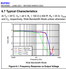
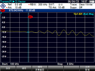
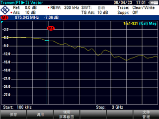
I have purchased a BUF802RGTEVM to measure the bandwidth of the BUF802 chip. During the experiment, I used a signal source, an oscilloscope, two transmission lines, and BUF802RGTEVM. The signal source provides a sine signal with a power of 4dBm and a frequency set at 2GHz. The overall gain is -6.4dB. Then I used a network analyzer to measure the line loss of the two transmission lines. At 2GHz, the total line loss of the two lines is about -1.7dB, which means that the loss on the BUF802RGTEVM reaches -4.7dB. This clearly does not comply with the 3GHz bandwidth mentioned in the data manual. We hope you can provide some suggestions.

Thank you

  • use a network analyzer with full calibration. And at 3GHz you should expect to be down 3dB, at 2GHz, pretty flat, mayb dwon about 0.5dB


  • Hello!

    We have carefully studied the images in the data manual, and the current problem is that I cannot replicate the results in the data manual through experiments. The following are the S12 parameters of the sample plate that we measured by connecting the network analyzer to the input and output ports of the sample plate. These two figures are respectively BF working mode and CL working mode. According to my measurement results, in CL operating mode, the gain is already below -3dB after 1.5GHz. If possible, could you provide some details of your experiment? For example, standard testing methods, instruments used, and so on.

    Thank you

    BF working mode:

    CL working mode:

  • Hello,

       This thread continues this discussion: 

    e2e.ti.com/.../buf802rgtevm-the-bandwidth-can-not-reach-3ghz-index-in-the-datasheet 

       Let me know if the latest reply solves your issue.

    Thank you,

    Sima

  • Do you have the files of our AC evaluation board to be shared here.

    Also please note the -3dB  mentioned @ 3GHz  in the datasheet is the attenuation @ 3GHz compared to that of the attenuation @ DC. At DC as per datasheet the attenuation is 0.97 V/V which means a attenuation of -0.26dB attenuation at DC itself.

    Also the EVM has the composite loop with input series resistance , inductance in 50 ohm path etc to ensure along with S21 , S11 achieved is also better than -10dB . Hence the EVM composite loop trades off some of the S21 performance to achieve better S11. However the BUF802 datasheet mentions S21 purely with BUF802 in mind and does not include the composite loop.