This thread has been locked.

If you have a related question, please click the "Ask a related question" button in the top right corner. The newly created question will be automatically linked to this question.

INA185: Use 2 current sense op amps for fully differential ADC on F28379D

Part Number: INA185
Other Parts Discussed in Thread: THS4521, TINA-TI

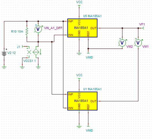
In order to use the 16-bit mode of F28379D ADC, I would like to use 2 INA185 connected in reverse (VDD = 3V, output signals are biased to 1.5V) to create a differential signal to feed into ADCA4 and ADCA5 of the LAUNCHXL-28379D. Simulations show that this is possible but I would like to hear your comments on various potential scenarios that could affect this topology.

PS: I tried to use the fully differential THS4521 but the output signal is distorted near the rails and voltage offset at low signal level is not good compared to the above circuit.

  • Hello,

    This will work (granted you calculated the current and shunt correctly you do not call out the current magnitude needed to be measured). There maybe problems with bias currents causing error in your measurement by paralleling two INAs this will be more important at low Vshunt.

    Another way to get differential output is to take the measurement from the output with respect to Vref. VM2 pictured below. Picture is just for reference.

    Attached is the TINA-TI file in case you want to play around with it.

    /cfs-file/__key/communityserver-discussions-components-files/14/INA_5F00_185_5F00_dif_5F00_out.TSC

    Regards,

    Cas

  • Hi Castrense, thank you for comments. I'm using 16ohm shunt to measure the secondary side of a current transformer (ratio 5A/2000), maximum current to measure is about 3.6 mA, minimum 0.025 mA.

  • Hello,

    The INA185 has a BW of 350kHz keep this in mind for the AC current you are trying to measure.

    Doing some quick calculations using a 16 ohm shunt at your minimum current 0.25mA you will get a Vsense of 400uV. The offset of the INA185 typical is 100uV (Vsense = 0V and Vcm = 12V) this will give an error of around 25%. If this is not tolerable you will need to choose a part with better Vos or increase shunt resistance. 

    Regards,

    Cas

  • Hi, thank you for your notice.

    Just a quick clarification, Vsense should be 4mV at 16ohm and 0.25mA, not 400uV, right? And if there is a significant Vos compared to Vsense, the differential process should cancel it out a bit, correct? 

  • Hello,

    1, Yes 16*.25mA = 4mV. I made a mistake I meant 0.025mA as you referenced before. Sorry

    2, No, the differential signal will help with any noise picked up by the traces will be common to the differential signal. If you use your 2 INA185 approach it could be worse if the INA185's have complementary offset as one has negative offset and the other has positive offset.

    You could do a calibration to have Vos not be a factor.

    Regards,

    Cas

  • Hi,

    Thank you very much for your comments. I have moved on to use a fully differential amplifier to simplify the design. Cheers.