This thread has been locked.

If you have a related question, please click the "Ask a related question" button in the top right corner. The newly created question will be automatically linked to this question.

INA101: Output starts jumping randomly after a few minutes

Part Number: INA101
Other Parts Discussed in Thread: OPA177,

Hello,

I'm using two INA101HP (DIP package) stages in series.

The signal from a sensor (~100Ohms) as input for the Amplifier is 0-500uV AC with a DC-offset in the range of 0-120mV. The input signal is floating therefore a 1MOhm resister is connected at pin12 (+Input) to GND, to provide the path for the input bias current.

Power supply is at +/-15V. The gain of each stage is G=100. No input offset compensation.

The first stage is using the output offset compensation circuit with the OPA177 exactly as shown in the datasheet with adjusted resistors. The output offset compensation is used to get rid of the input DC-offset in the range of the 0-120mV (AC-coupling the signal is not an option). The second stage further amplifies the 0-500uV AC signal without any offset compensation.

After a few minutes the output of the first amplifier stage starts jumping randomly. Pin 14 (common) shorted to GND (replacing the OPA177 offset compensation) then doesn't resolve the problem

Does it mean the INA101 experienced some kind of degradation? What could be the cause of degradiation and is there anything else to consider?

Best,

Beat

  • Hi Beat,

    the INA101 shows a rather high input bias current. The 1M resistor for the input bias current may be too high. Can you decrease it for a test?

    "Floating" can also mean that the input sees a too high common mode input voltage which makes the INA101 go into saturation sometime. Can you mesure the common mode input voltage (voltage across the 1M resistor)?

    Kai

  • Hi Kai,

    Thanks for your quick reply.

    1. With open input and the 1M resistor the voltage across the resistor is -0.18V. 

    2. Replacing the 1M with 100k the voltage across the resistor is -0.15V, still with open input.

    3. Configuration 2. with 100k at input across pin 3 and pin 12. At the output the voltage at pin 1 against GND measures 5V. A current of 0.5uA seems to flow through the 100k input resistor.

    What could explain this?

  • Hi Beat,

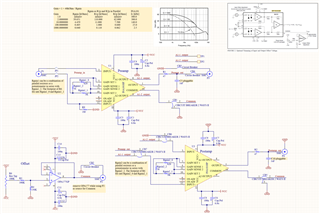
    Could you send a schematic of the circuit you have discussed above?  While your description is thorough, there are still some questions about the connections that would be much easier to cover from a schematic view.

    Thanks,
    Mike

  • Hi Michael,

    Sure, here it is.

  • Hey Beat, 

    I am looking at this in simulation. I wanted to confirm with you my understanding based on your description. 

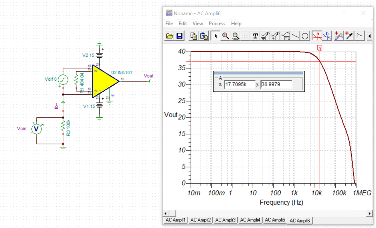
    To start, my basic circuit is in a gain of 40 dB or 100 V/V. 

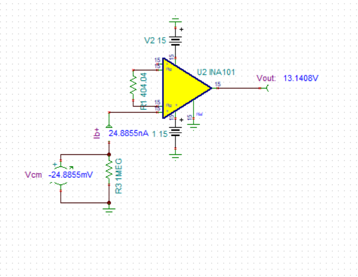
    1. With open input and the 1M resistor the voltage across the resistor is -0.18V. 

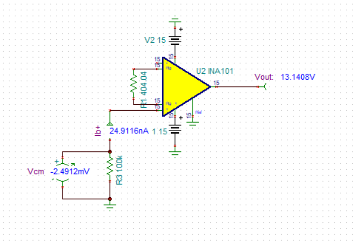
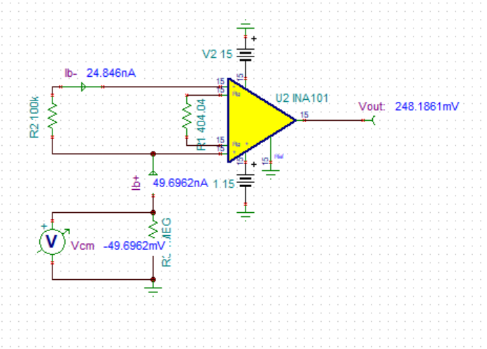
    Below I have the input signal disconnected and the 1M resistor tied to the non-inverting terminal. The output voltage near the supply rail is a result of the other input floating. Let me know if my interpretation is incorrect and I can adjust my circuit in order to simulate your observations. Note that the Ib is about 25 nA resulting in the 25 mV across the 1M resistor. 

    2. Replacing the 1M with 100k the voltage across the resistor is -0.15V, still with open input.

    3. Configuration 2. with 100k at input across pin 3 and pin 12. At the output the voltage at pin 1 against GND measures 5V. A current of 0.5uA seems to flow through the 100k input resistor.

    Is my understanding of the 3 scenarios above correct? Here is the Tina Ti simulation to help us during this debug. 

    INA101.TSC

    Best Regards, 

    Chris Featherstone

  • Grüezi Beat,

    looks like the INA101 is damaged. I would replace the INA101 by a fresh one and check again.

    To prevent damage in future, it may be helpful to add some protection to the inputs. Diode clamps to the supply rails in combination with a current limiting resistor and a low pass filter cap can be enormously helpful.

    But the following issue is even more significant: From the schematic it seems that a cable is connected to P1 via a SMC connector? Keep in mind that any ESD hitting the cable shield of this cable will directly run into the +input of INA101 and may damage it. When using a cable in this way the cable shield can no longer shunt ESD to signal ground and by this protect the electronics, but will inject ESD directly into the electronics.

    One remedy is to use a shielded twisted pair cable, with the twisted pair connecting to the sensor and the cable shield connecting to signal ground. This would also improve the suppression of EMI at the input of INA101. 

    Best you combine both techniques, using a shielded twisted pair cable and adding a protection and filtering circuit to the inputs.

    Kai

  • Grüezi Kai, 

    Do you have close relations to Switzerland / Swiss German Grinning?

    Thanks for your suggestions. I' going to replace the INA101 and add at least the shielded twisted pair cable.

    Then I will check Chris' simulation in practice and discuss here my experience.

    And to gain from your experience, do you have a proposal for good clamping diodes?

    Best Regards,

    Beat

  • Hi Beat,

    when I look out of my window I see the Rhein, Switzerland and a nuclear power station... Relaxed

    Kai