This thread has been locked.

If you have a related question, please click the "Ask a related question" button in the top right corner. The newly created question will be automatically linked to this question.

INA849: Frequency response and the connection of the Ref

Part Number: INA849

Hi Team,

This is a question about how to use the instrumentation amplifier INA849.

① Regarding the connection of the Ref terminal
When I tried to output only the positive voltage side by shorting the Ref terminal and the Gnd terminal (-power supply terminal), the output response changed around 1MHz. Is it not possible to use it like this? For a gain of 1x, the output may be greater than the input.

②Frequency response of output when dual power supply is used
Since ① did not work well, I tested it by applying a Ref voltage with a dual power supply, but the output response also changed around 3MHz.

If you have a detailed recommended circuit, could you send it to me? Thank you very much.

question.pptx

Best Regards,
Tom

  • HI Tom,

    On circuit 1, the INA849 is powered with unipolar supply, with +VS=+17V, VS=GND, and  REF = GND.  The input signal is ±5V bipolar, with input common-mode centered at GND.  This condition is outside the input common-mode and outside the output voltage swing specification of the INA849. 

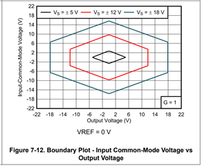
    Please note, the input common-mode operating input range requires headroom > 2.5V from the supplies; and the output swing requires at least 150mV headroom from the supplies.  The input range depends on the supply voltage, common-mode voltage, differential voltage, gain, and reference voltage.

    In this case, with REF=GND the device will require bipolar supplies with a negative supply -VS more negative than -7.5V to place the device inside of linear range, for example, +VS=+12V and -VS=-12V.

    See Figure 7-12, boundary plot - - "Input Common-Mode Voltage vs Output Voltage":

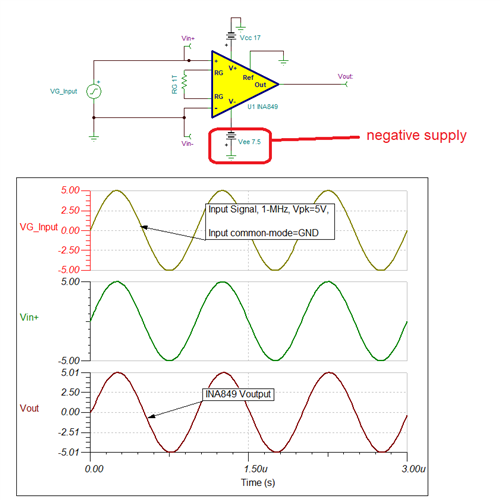
    See simulation with the modified circuit with Vs- = -7.5V and ±5V input signal at 1MHz, where the device works properly:

    TINA simulation:

    INA849.TSC

    On circuit 2, same as above, you will require a negative supply more negative than -7.5V to support a bipolar input signal with ±5Vpk amplitude and input common-mode voltage at 0V.  This circuit works well for the 1-MHz, ±5V bipolar input signal, with input common-mode centered at GND. 

    However, when using Vin= 5Vpk signal with the higher signal frequency of 3-MHz, the input signal exceeds the slew rate of the device.  The INA849 slew rate is specified as 35-V/us typical.  Hence the maximum frequency supported for a ±5Vpk amplitude signal is less than < ~1.11-MHz. 

    Thank you and Regards,

    Luis

  • Hi Luis,

    Thank you for answering my questions.
    I roughly understood how to use the amp correctly and modified our circuit.

    I have a few additional questions.

    ・Shouldn't REF and GND be connected even when half-wave rectification based on GND is applied to the input?
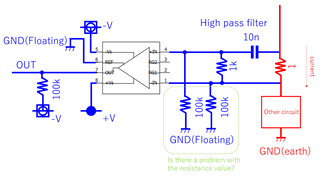
    ・I would like to set the high pass filter before the input, is there any problem about current escape pass? Please check the attached figure.
    ・Is there any possibility that the lifetime will be shortened due to factors the continuous input of several volts at 3MHz(other than heat problem)? Also, is there a difference between putting the high-pass filter on the input and putting it on the output?

    Best Regards,
    Tom

  • Tom,

    I'm helping out Luis while he is traveling.  

    • Yes, you are correct.  For proper operation of the device you cannot leave the reference pin floating.  The output will be referenced to that level.  Vout = G(VinP - VinN) + Vref.  If Vref is floating, the output will be indeterminant.  
    • I'm not sure what you mean by "current escape pass".  However, using a high pass filter on the input is a reasonable thing to do.
    • As long as you are not violating the absolute maximum ratings of the device, applying a 3MHz signal should not shorten the lifespan.  You are correct that elevating the temperature of the device will accelerate the ageing of the device, but I doubt that you will see much heating from that signal (assuming the levels do not violate operating conditions).
    • Placing a high pass filter on the input will block DC at the input.  If the DC is a high level this could overdrive the device.  If the DC is within the device range it will not cause a problem.  Placing the filter on the input can prevent the DC overdrive problem from happening.  If DC is low it doesn't really matter where the filter is placed.  In general, the filter is placed on the input to block the DC and allow for higher gain of AC signals.

    I hope this helps.

    Best regards, Art Kay

  • Hi Liu,

    not sure whether I understand you correctly, but operating the INA849 with floating ground may be dangerous for the INA849. You risk a damage. See the built-in protection diodes of INA849 (only one drawn). If the INA849's ground float too much, the input protection diodes become forward biased and if there's no input current limiting the INA849 will become damaged:

    It's true that the two 100k resistors provide a path for the input bias currents of INA849 and becuse of this are useful at the inputs of INA849, but they do not provide any protection against overvoltages. You would need current limting resistors in series to the inputs (green rectangles) to limit the input currents to below 10mA. See the absolute maximum ratings. Even more useful were diode clamps from the inputs to the supply rails. But then, of course, the supply voltage lines must be able to absorb these clamped currents.

    Experience has shown, though, that these sorts of floating circuits run into big problems when ESD, Surge and Burst are reaching the circuit. Because of that, I would recommend to use an isolation amplifier:

    https://www.ti.com/isolation/isolated-amplifiers/products.html

    They are specialized for exact these applications.

    And since you don't need a DC coupling, another remedy may be the use a transformer coupling at the input. This also would allow a full galvanic isolation.

    Kai