This thread has been locked.

If you have a related question, please click the "Ask a related question" button in the top right corner. The newly created question will be automatically linked to this question.

LM2903B-Q1: Comparator hysteresis calculation

Part Number: LM2903B-Q1
Other Parts Discussed in Thread: LM2903B

Hi Expert, 

I'm calculateing the value of the hysteresis input with LM2903B.

However I found the difference between similation results and caliculation results.

Could you please let me know the reason of those difference?

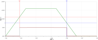
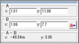
<Similation results :Tina_TI>

Rhys=500kohm

Rtop=100kohm

Rbottom=47kohm

Vref=3V

Vpullup=5V
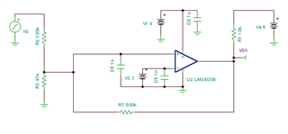
Vr= 11.06V

Vf= 7.7V

<Caliculation results>

Is  my following caliculation correct?

Vr =  Vref x (Rtop + Rbottom // Rhys) / (Rbottom // Rhys) = 9.983V

Vf = Vref + (R1/R2)xVref - (R1/R3)x(Vcc-Vref) = 8.983V

Could you please give me your advice?

Thanks

  • Hello Mukuno,

    Remove C6 and try again. Also add a monitor to the positive comparator input to see the effect.

    Adding a capacitor to the positive node when using hysteresis adds a delay to the feedback and can actually cause problems. I know you thought it added filtering, but it is actually detrimental to the hysteresis.

  • Hi Paul-san,

    Thank you for your support.

    It was not improved with removing input cap (C6).

    I tried to monitor input signals. it seems to have some delay.

    If the delay is 0sec, I think, the histerisis value will match to the caliculation values.  

    Do you have any advice for this delay?

    Thanks.

  • Hi Yusuke-san,

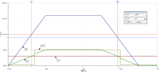
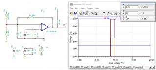
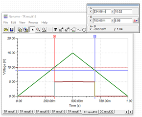
    I recreated your circuit and ran a DC transfer test, it looks like your simulation and your calculations of Vr and Vf match.

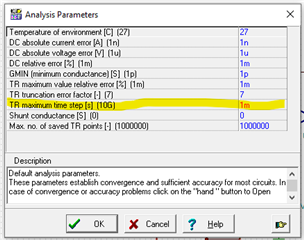
    The delay you are seeing is an artifact of how TINA runs its simulations. By default, the accuracy of the simulation is a little bit off, but there is a way to improve it. You'll want to go to Analysis/Analysis Parameters and then edit the line that says "TR maximum time step [s]" to about 1/1000th of the time range you're looking at. For instance, for a 1s range, you'll change the max time step to 1m. 

    I've also included an image here of a transient analysis showing the Vr and Vf you calculated after changing the maximum time step.

    LM2903B_hys_sim.TSC