I'm looking for a little clarification on the PD pin and what to do with it.
1. The data sheet states this pin is available in the use case where applications need to put the device into a low power state. I want to clarify that this is the only use case. For example, some ICs have a reset pin that needs to stay asserted until the power supply rails come up. I just wanted to make sure the state of this PD pin is independent of the power supply rails coming up.
2. We do not have a low power need in our application. However, there appears to be some conflicting information in the data sheet on what to do with the pin in this case.
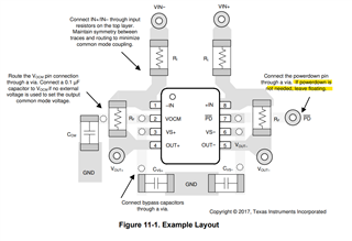
Figure 11-1 states if PD is not needed, leave it floating:
9.1.5 states if PD is not needed, tie the pin straight to the power supply.
The THP210 eval module schematic shows the pin tied to Vcc with a 10k resistor.
Please advise the optimum way to handle the PD pin if we don't need the power down feature and we want to be sure it deterministically comes up in normal, full power operation, with each power cycle.
Thank you.


