This thread has been locked.

If you have a related question, please click the "Ask a related question" button in the top right corner. The newly created question will be automatically linked to this question.

INA381: Input series resistor fails when device powered ON

Part Number: INA381

Hello All,

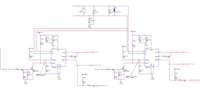
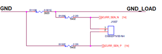
I am using INA381 device for measuring & detecting OC for bidirectional current. The devices are connected as shown below. When the board is powered the series resistor degrades and ultimately the resistor damages and shows >20kohm. May know what would be the reason for the same. the bias currents are max. 80uA from each device which should not dissipate more power for the resistor.

Thanks in advance.

Anand M

  • Hi Anand,

    please show a complete schematic including the GND pins of INA381 and including the shunt resistance.

    Kai

  • Hello,

    Nothing obvious is standing out in your drawing. Having a complete schematic as Kai mentioned would help us help you. What is the leakage of the TVS diode you have as well as the breakdown voltage? Could you be activating the TVS causing current to rush in and damage the resistors? 

    What is the load of your circuit?

    Regards,

    Cas

  • Dear and

    Thank you for the response, Below is the schematic for you reference, kindly let me know you feedback.

    The TVS breakdown is 5V and it leakage is 1uA, Is TVS recommended to use across inputs or as common mode protection.?

    Thanks,

    Anand M

  • Hi Anand,

    unfortunately, the schematic isn't showing the major point: How the potentials applied to the shunt (and to the inputs of INA381) are related to the ground of INA381 (B-GND)?

    Keep in mind that the potenials at the inputs of INA381 must not go more negative than -0.3V below to B-GND. But from your schematic the inputs seem to float freely without any limit.

    Kai

  • Dear Kai,

    Thanks for the response. We see the damage of the resistor even when there is no current flow through the shunt. The alert outputs are also latching up during board power up. Below is the shunt connection for your reference as you requested

    GND is power ground and B_GND is connected to GND through a choke for all AD sections.

    Let me know if any clarifications required.

    Regards,

    Anand M

  • Hi Anand,

    GND is power ground and B_GND is connected to GND through a choke for all AD sections.

    I would remove this choke and replace it by a short circuit. Also, have B_GND and the INA381 lose to GND. Any distance and any inductance between B_GND and GND can cause destryoing inductive kickbacks and other unwanted voltage drops.

    Kai

  • Hello,

    I would agree with Kai having the INA381 B_GND directly connected to GND with as least inductance is best practice. Violating abs min for any pin on the device will result in damaging the part.

    Regards,

    Cas

  • Dear Kai and Castrense,)

    I have shorted the GND and BGND at the choke, the problem still exist. But when I changed the resistor to 0ohm, the resistor doesn't show any abnormality of rise of the resistance/failure. Also I tried to see if there is any higher current to the input by putting DMM in ammeter mode across the resistor pads (without series resistor), but didn't not measure any current (it is may be few nA)

    I don't see any damage of the IC for prolonged power up conditions, and I verified the input to output gain (Vout) and it looks ok.

    Could you suggest if there is any other aspect which I could do and check,

    Regards,

    Anand M

  • Hello,

    I noticed j1007 what is the purpose of this connector does it connect somewhere?

    Regards,

    Cas

  • Dear ,

    This connector will get connected to the AFE for current measurement. The issue is observed even without connecting this connector to AFE,

    Regards,

    Anand M

  • Hi Anand,

    only for clarification: By the "series resistor" that get damaged you mean the two 2R2 resistors at the shunt, right? Which one gets damaged?

    Also I tried to see if there is any higher current to the input by putting DMM in ammeter mode across the resistor pads (without series resistor), but didn't not measure any current (it is may be few nA)

    If the destroying current peak would only flow during the brief period of power-up, then you would not be able to see the current peak with a DMM. DMMs are usually too slow. But you can use a scope to measure the voltage drops across the 2R2 resistors during power-up.

    I think that something unwanted is going on during power-up. It looks like that a too high current is flowing through the 2R2 resistors during power-up. A too high current can flow via three paths:

    1. Through the input of INA381 when applying an input voltage becoming more negative than -0.3V. This can be detected with a scope measuring the input voltage relative to the ground pin of INA381.

    2. Through one of the 10nF caps close to the shunt. But this seems to be less probable because the current would last relatively short. This can be detected with a scope measuring the voltage drop across the two 2R2 resistors.

    3. Through the TVS close to the shunt. This again can be detected with a scope measuring the voltage drop across the two 2R2 resistors.

    And I think that all this comes from an unsuited cabling arround the shunt or from a massive grounding problem. To confirm this a photo of your setup would be needed. We need to know where the shunt is relative to the INA381s. And we need to know where GND is relative to B_GND.

    Also, what load is connected to the shunt? Or by other words, what current is flowing across the shunt during power-up?

    Kai

  • Dear Kai,

    The behavior not seen i.e. damage of the series resistor when I short the BAT- and B_GND. It looks the inductance creating clamp diode to breakdown and high current is flowing through the resistor and INA381 pins. I verified in 5 fresh boards with directly shorting the ground and no damage observed so far.

    Also this consideration helps me to optimize our grounding scheme. Thanks and appreciate for the support.

    Regards,

    Anand M