Are there any application circuits currently available for a programmable +/- 1mA current source with high output resistance (preferably, using the INA326 op amp)?
Thanks,
BC
This thread has been locked.
If you have a related question, please click the "Ask a related question" button in the top right corner. The newly created question will be automatically linked to this question.
Hello BC,
There is an application circuit on page 16 of the datasheet of the INA32 instrumentation amplifier. By changing the resistor values you can get the current from +/-5mA to +/-1mA.
Will this work for you?
Best regards
Thomas
Hi Thomas,
Thanks alot for the suggestion. It looks like Figure 15 on page 15 would be a better fit, as I can't have any input into the DAC. I should still be able to change the resistor values to get the current from +/-25uA to +/-1mA, correct? Thanks again!
Regards,
Brandon
You can also use the application in Figure 15 as a start. Let me know how everything works out for you when you have completed your system!
Best regards
Thomas
Brandon,
You can use TINA-TI to simulate this application. The model is availible on the overview page of the INA326 (http://focus.ti.com/docs/prod/folders/print/ina326.html#toolssoftware).
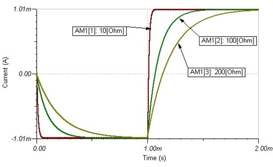
I have also created a small simulation to show you a +/-1mA current source with this part (simulated with different load resistors.)
Hi Thomas,
Sorry for not getting back sooner. Thank you for the information.
What does the asterisk at the 100 ohm resistor mean? I can't figure from the help page what it stands for. I get the same 1mA current through the ampmeter when I change the 100 ohm resistor up (even to 10M ohm, which is roughly the size of my load) or down. But when the asterisk is not there, I don't get 1mA.
Thanks again,
Brandon
Hi Thomas, Sorry for not getting back sooner. Thank you for the information. What does the asterisk at the 100 ohm resistor mean? I can't figure from the help page what it stands for. I get the same 1mA current through the ampmeter when I change the 100 ohm resistor up (even to 10M ohm, which is roughly the size of my load) or down. But when the asterisk is not there, I don't get 1mA. Thanks again, Brandon
Hello Brandon,
The asterisk denotes a "control object". This allowed him to vary the value of the resistor in a single simulation. I have re-run his simulation and labeled the values for your convenience.

Thank you Pete,
Yes, I was thinking that was the case. How can I insert a control object into the schematic editor?
I assumed that the application circuit would be one that was independent of the load, so I didn't mention it to Thomas at the beginning. It can me modeled by a 10M resistor in parallel with a 200nF cap, together in series with a 10K resistor. I see that when I attach this to the circuit, the current completely changes. Is there an application that is independent of the load using the INA326?
Thanks again, Pete, for you help.
Regards,
Brandon
Hello Brandon,
Please note that parts of my screen captures may differ from yours since I'm using an Industrial Version of the software.
Click on this toolbar icon (Select Control Object)
![]()
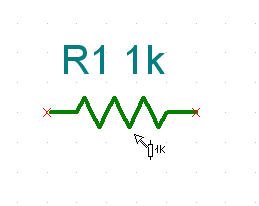
From there you can then click on a component, such as a resistor.

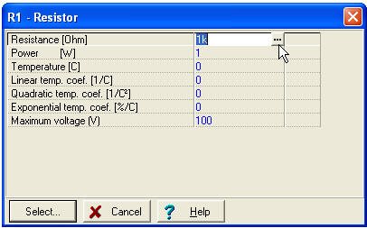
After selecting the component it will bring up the following window:

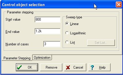
From there you can click on the ellipses and obtain the following window:

In this window you can specify the nature of your sweep.
We will have to look at the rest of your questions and get back with you.
Hello Brandon,
I have now read the entire thread.
At DC, in order to provide 1mA to a 10Mohm load the output of the amplifier would have to reach 10kV. Our amplifiers cannot do this. Perhaps I am misunderstanding your application.
At 1kHz (the BW of the INA326), the impedance of your load is 10.031676kohms. At 1mA this would still require an output voltage beyond the maximum recommended value for the power supply.
Perhaps you could share more about the application itself to help us better understand what you're trying to accomplish overall.
We are trying to deliver bipolar current pulses through an electrode. After discussing this issue, I was able to clear up some things. The electrode-solution interface typically reaches the 10M ohm range (max), but can (and more often is) in the 10k ohm range (min). 1mA is the max current to be produced, and we would deliver this through a load at only about 10k-80k (so max of about 80V). 10-80uA would be the range of current we would deliver through a 1M load.