This thread has been locked.

If you have a related question, please click the "Ask a related question" button in the top right corner. The newly created question will be automatically linked to this question.

XTR105

Other Parts Discussed in Thread: XTR105

Hello Friends,

Need some help here..

This is the third time I have posted this, without any response. Wakeup, TI !

Alternator windings have provision of Pt100 3 wire RTDs embedded in them for measurement of winding temperature.

I am using XTR105 as per Figure 3 of data sheet http://focus.ti.com/lit/ds/symlink/xtr105.pdf. Temperature Range is 0 to 200 degC and Rz, Rg, Rlin1, Rlin2 have been selected as per Table 1. Additional filtering is done as per figure 5, with values as shown in the said data sheet.

The connection from the RTD at the Alternator end to the XTR105 is through a shielded cable approximately 8m long, with the shield terminated to the chassis at the control panel end.

It is experienced that the current output of the XTR105 varies continuously, resulting in a fluctuating display of the order of 30 degC. This triggers false alarms of winding overheating, and also makes recording the temperature difficult for the panel operator.

Any suggestions, please ? Thanks,

JayantD

  • Hello JayantD,

    I apologize for your troubles with the forums. 

    Although I can put together a schematic based on your description, would you please share your exact schematic so I can see how you've connected everything to the XTR105?

    Since the RTD is located in a noisy environment such as an alternator I'm concerned with the fidelity of the input signal getting to the XTR105.  Have you verified that the input signal is constant when the output of the XTR105 is varying? 

    Would you please provide a few examples of a measured nput voltage and the resulting output current variations?

    Please help provide some insight into these questions and we'll work to get this figured out.

    Regards,
    Collin Wells
    Precision Analog

  • Hello Colin,

    Thanks for your response.

     I will arrange to attach some details through my engineer Ganesh, as I am presently at a different location at the moment.

    We suspect that the input signal itself is varying. The XTR105 circuit by itself performs satisfactorily in other applications which are less noisy. We have to find a solution for this. 

    Regards,

    JayantD

  • Hello;


    XTR105 circuit diagram


    XTR Readings :


    RTD Readings took using fluke calibrator(Resistance Source in Reading  is Fluke meter).

    Thanks & Regards;
    Ganesh
  • Hello Ganesh,

    Thank you for your schematic and the results.

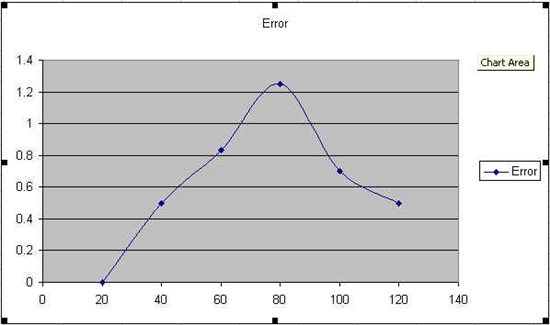
    JayantD had originally brought up an issue where the output of the XTR105 was varying enough to produce up to 30degrees of temperature error when back-calculating the temperature.  For a 0-200 degree 4-20mA output application, this would correspond to: ((0.02 - 0.004)/200)*30 = 2.4mA of output variation at any time.  The data you've provided shows a changing error with temperature, but does not describe the same symptoms that JayantD described.  Are you experiencing the same variation as Jayant on the output of the XTR?

    Otherwise, I've plotted the error of your circuit output below.  Although it is not as parabolic like a standard RTD error, it does have a similar shape making me question the correctness of the Rlin1, Rlin2, and Rg resistor choices.

    In a 3-wire RTD application with a 0-200C desired temperature range, the correct values for Rz, Rlin1, Rlin2, and Rg are:
    Rz:  100
    Rg:  158
    Rlin1: 16200
    Rlin2:  18700

    Your schematic indicates the following values:
    Rz:  100
    Rg:  500Ohm potentiometer
    Rlin1: 24000
    Rlin2:  22000

    Is this design meant for a 0-200degree RTD temperature range?  If so, please try your measurements again with the values above.  If not, please provide the following information:
    Minimum Temperature
    Maximum Temperature
    Measured Value of the Rg potentiometer (Tuned in value is not on the schematic)

    I will double check your component selection based on the information above.  Also, why use a potentiometer for the Rg resistor?  Were you not able to find a close enough standard value or are you trying to trim the error down with the potentiometer?  If it is the latter then beware that the value of the Rlin2 resistor depends on the value of Rg and if you change Rg you will have to make a corresponding change to Rlin2 or you will experience unwanted non linearity errors.   

    Please provide some insight into the questions raised in this post and we will get this worked out.

    Thanks and Regards,
    Collin Wells
    Precision Linear

  • Hello Collin;


    The readings attached are  XTR105 output when input is given by Fluke calibrator. 
    At present we dont have readings with RTD inside winding. We will inform actual error after taking readings from site. 
    The 500 ohm potentiometer is a provision on the PCB for future  non standard requirement. 
    Actual values soldered on PCB:
    Rg = 117 ohm
    Rz = 100 ohm
    Rlin1 = 22000 ohm
    Rlin2 = 24000 ohm
    Minimum Temperature 0 deg C
    Maximum Temperature 200 deg C


    Thanks & Regards;

    Ganesh

  • Hello Ganesh,

    Thank you for helping me understand how the data was collected.  We can work on the issue Jayant brought up after we finish reducing the errors you're experiencing with a controlled input from the Fluke Calibrator.

    I believe the majority of the errors you're experiencing are a result of incorrect values for Rz, Rlin1, Rlin2, and Rg.  The correct values for all three of these components enable the linearization engine in the XTR105 to correctly achieve the 40:1 improvement over a nonlinearized RTD.  All three values must be set based on the temperature range to achieve the proper results.

    For a desired RTD temperature range of 0-200C, the correct values for Rz, Rlin1, Rlin2, and Rg can be seen in Table 1 on page 8 of the XTR105 datasheet and are listed below:
    Rz:  100
    Rg:  158
    Rlin1: 16200
    Rlin2:  18700

    Your schematic indicates the following values:
    Rz:  100
    Rg:  500Ohm potentiometer
    Rlin1: 24000
    Rlin2:  22000

    Your values are incorrect and need to be changed.  Please change your resistor values to the values listed above and re-take your measurements. 

    Let me know the results and then we will work on the noise issue Jayant described.

    Thanks and Regards,
    Collin Wells
    Precision Linear

  • Hello Colin,

    Let me first apologize for an error from my side  - the range is 0 to 150 degC against 0 to 200 degC as mentioned earlier.

    I have used the TI tool xtr_calc.xls (slvc094.zip) to calculate values of Rg, Rlin1 and Rlin2.

    with R0 = 100 , T1 = 0 and T2 = 150 entered in J4, J7 and J8 respectively, the spreadsheet returns the following values.

    RZ 100
    RG 117
    RLIN1 21807
    RLIN2 24364

    Thus Ganesh has reported the values which have actually been soldered on the board. We have used 22k and 24k for Rlin1 and Rlin2, as the displayed accuracy is required to be within +/- 2 degrees.

    Thanks and best regards,

    JayantD

    Ganesh, please take a fresh set of readings with above values and upload a s a p so that Colin can suggest a proper solution for us.

  • Hello Sir;


    As Jayant sir suggested i took fresh set readings.


    Thanks & Regards;
    Ganesh
  • Hello Colin,

    The alternator runs at 1500 RPM, generating 440 Vac 50Hz, 3 phase supply. we have tried routing the cable through a split ferrite, without any visible difference whatsoever.

    Hope this helps..

    Regards,

    JayantD 


  • Hello Jayant,

    Thank you very much for the updated information and system specifications. 

    Ganesh's most recent measurements seem consistent with what I would expect for the XTR105 if using rounded values for resistances.

    Using the same XTR_CALC.xls tool that you've used already I entered in your system specifications and received the same values as you for the RG, RLIN1, and RLIN2.  Then I modified the calculated values for RLIN1 and RLIN2 replacing them with the values you've selected of 22k and 24k respectively.  It should be noted that I have still not received confirmation from Ganesh or yourself regarding the value of Rg that you have selected for your system, so I used 117Ohms as recommended by the calculator.  Then I entered in tolerances of 0.1% for each of the four resistors and added the typical errors for RLIN, IREF1, IREF2, and GAIN based on the datasheet typical specifications. 

    The calculator predicted a total output error of up to 0.18% FSR which equates to a temperature error of (0.0018 * 150) = 0.27C.  By changing the resistor tolerance to 1%, the calculator predicts a total output error up to 2.5% FSR which equates to (0.025 * 150) = 3.75C.  Therefore without knowing more about your system I believe that the recent data Ganesh took is valid and appropriate. 

    We've confirmed that the output error is in alignment with the calculator/spec using a controlled source so let's move on to the noise issue that was originally described.  You've mentioned that you're using an 8m long shielded cable with the shield connected to the CHASSIS GND.  Is the cable between the XTR105 and the main system receiver or is it between the RTD and the XTR105?  If the cable is not for the RTD, how far is the RTD from the XTR105 and are it's connections shielded?  If so, what potential is this shield connected to?  Have you tried measuring the RTD resistance with a lab multimeter while in the active alternator to see if the data from the RTD is constant.  Also please probe the RTD signals with a oscilloscope to see if you detect the noise there or not.   

    Could you provide additional details about the cable you're using?  Are the signals twisted together inside of the cable?  Are the signals individually shielded in the cable or does the shield contain all of the wires?  How much of the sensor/cable is outside of the shield (in distance)?  Have you tried connecting the SHIELD to other potentials in the circuit besides the chassis GND connection?  Is there improvement when the shield is connected to the GND connection used by the 4-20mA receiver or when connected to the IOUT signal itself.   

    I'm trying to get a better understanding of where the noise is entering the system and if it is present at the inputs to the XTR105 or if it is getting coupled into the 4-20mA output of the XTR105.

    Thank you,
    Collin Wells
    Precision Analog 

  • Hello Collin,

    Thank you for your detailed reply.

    The RTDs are terminated in a junction box on the alternator. We have no idea whether they are shielded or not, because there is no shield terminal provided there. From the junction box we have a 10core shielded cable to the control panel, carrying signals of the R, Y, and B phase RTDs. On the control panel end there is an earthed amphenol connector. The cable shield is connected to the chassis through this connector. The cable length is approximately 8m. Inside the control panel, we have a 3 core twisted teflon cable going to the XTR105 PCB. The length of this cable is approx 1m. The routing is away from power cables.

    At the moment it may not be feasible to probe the RTD terminals with a scope while in active mode, but we will try our best and get some significant data on this.

    Thanks,

    JayantD

  • Hi Jayant,

    Thank you for the additional information.

    Let me make sure I understand the circuit. There are three RTDs inside of the alternator, one for each phase. All three RTD outputs are carried in one 10-conductor shielded cable. Each RTD is a three-wire RTD so there are 3X3 = 9 used conductors and one unused conductor. This cable is routed 8 meters before the three RTDs are somehow (not described) selected and the three RTD wires of the selected RTD are routed another 1 meter to the XTR105PCB.

    Is this correct? If so, how are the three sets of RTD signals multiplexed into the single XTR105 PCB?

    I'm not sure if you still need to probe the RTD signals. From what you've described the noise from the alternator is getting coupled into the XTR105 inputs through the 8 meter RTD cable. The low-pass input filters that you've designed have a fc = 1/(2*pi*1000Ohms*0.1uF)= 1591Hz cut off frequency which will not be very effective vs. the 1500RPM alternator. Try lowering the cutoff frequency two decades to 15.91Hz by increasing the capacitor values to 10uF. This will slow down the response time of the temperature measurements, but if it fixes the noise issue you can find the appropriate compromise between measurement response time and noise.

    That said, this system is somewhat backwards of the traditional implementation of the XTR105. Most XTR105 systems place the XTR105 very close to the sensor to keep the XTR inputs clean and then the XTR105 current loop output is routed on the long cable length between the XTR105 and the control system. The XTR105 and any other sensor electornics are powered from the loop supply and data is sent back on the loop return, this is the advantage of the "2-wire" current loop transmitter.  The output current from the XTR105 should prove much more resistant to noise coupling over a long cable than the high impedance inputs of the XTR105.

    If the additional filtering does not prove successful, you may want to rethink the overall layout of your XTR105 system.

    Regards,
    Collin Wells
    Precision Linear


  • Hi Collin,

    Thank you for your solution.

    The problem has been solved by a digital FIR low pass filter implemented in firmware. It was convenient to upgrade firmware rather than a hardware change.

    Thanks again for your support. Your tips are scheduled for implementation in the next hardware upgrade.

    Warm Regards,

    JayantD

  • Hello Jayant,

    I'm glad you have found a solution.  Would you please share the cutoff frequency and order of the FIR filter that you implemented to solve this issue?

    Thank you,
    Collin Wells
    Precision Analog

  • Hello Collin,

    The working solution is a 64 tap 10Hz filter, implemented with a dsPIC30F3013. The display is refreshed three times per second.

    Best regards,

    JayantD