This thread has been locked.

If you have a related question, please click the "Ask a related question" button in the top right corner. The newly created question will be automatically linked to this question.

BUF802RGTEVM: The bandwidth can not reach 3GHz index in the datasheet

Part Number: BUF802RGTEVM
Other Parts Discussed in Thread: BUF802

hi team,

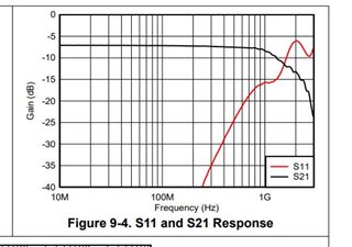
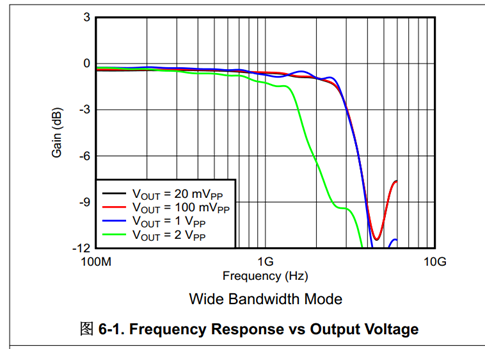
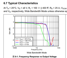
we are buying a test board and testing the bandwidth of BUF802RGTEVM. By the data sheet, the bandwidth will be reaching 3GHz which is shown in following picture.

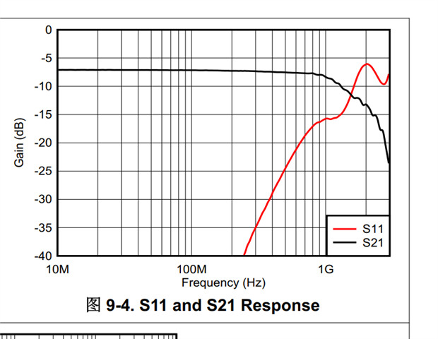
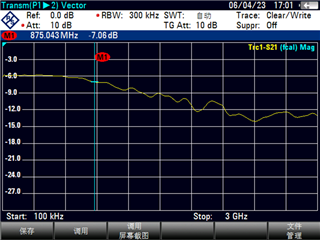
But we use the spectrum analyzer to test the S21 of the test board both in BF mode and CL mode, the 3dB bandwidth can only be 1.5 GHz.

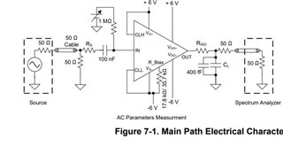
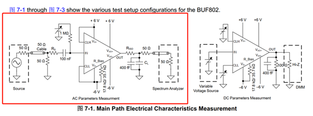
I want to know what is the test condition and configuration for figure.6-1 and if it is normal for our testing results.

Thank you in advance.

  • Hello SY,

      Can you show a picture of your setup (cabling + EVM)? Also, was the EVM modified?

    Thank you.

    Sima

  • Hello Sima,

    I use VNA to test the S21 of EVM. S1 connect to input while S2 connect to output of EVM. The setup is shown as followed,

    The attention of the RF coaxial will be less than 1 dB in the range of [DC, 3GHz]. But the attenuation of S21 is 7dB under the test.

    The EVM is not modified. Is there the attenuation of cable have been considered under the test for index of the datasheet ?  

  • Hello SY,

      Thank you for the block diagram. A 50 ohm matching impedance for a total of 100 ohms is considered for total attenuation in the measurement. AC parameters measurements specified in the datasheet are taken using the BUF802RGTEVM Standalone Configuration:

      If using the BUF802RGTEVM Composite Configuration, the frequency response can be found in the datasheet pages 23 and 24 which does show similar frequency response of a 3dB bandwidth of 1.5 GHz.

    Thank you,

    Sima 

  • I see. The test board BUF802RGTEVM is consistent with fig.9-1 of datasheet in Composite Configuration. But in Standalone Configuration, the input impedance is a little different from the fig.7-1 of datasheet. From the following proposed circuit of test board and datasheet, we can see that Rs=25 ohm is missing from the proposed circuit in datasheet. I am not sure if it will affect the S21 result.

    The test circuit in BUF802RGTEVM

    The proposed circuit in datasheet of BUF802

    In datasheet, the 3dB bandwidth of S21 can reach 3GHz in Fig. 6-1. In my opinion, the test board BUF802RGTEVM which TI company provided should reach this bandwidth. But I don’t get the 3GHz bandwidth while the test bandwidth for BUF802RGTEVM in both Standalone Configuration and Composite Configuration can only be 1.5 GHz. I want to know what is the reason for it.

    What is more, you mentioned that the bandwidth can only reach 1.5GHz which is obviously lower than standard index of 3GHz by using the BUF802RGTEVM Composite Configuration. Is it means that the bandwidth of  Composite Configuration can not satisfy the 3GHz bandwidth index requirement?  We can not use it in DC-3GHz frequency band test.

  • Hello SY,

      I will look into ordering an EVM to test the standalone BUF802. The isolation resistor shouldn’t greatly affect the bandwidth. 
      
       For the composite configuration, that is correct. In this configuration, you will be able to use from DC up to 1.5GHz.

    Thank you,

    Sima 

  • Yes for standalone BUF802 without any composite loop you should be able to achieve -3dB number of 3GHz 

    However if you want to achieve good S11 and have the composite loop with the BUF802 , you will be able to achieve < 2Ghz of LSBW for -3dB.