This thread has been locked.

If you have a related question, please click the "Ask a related question" button in the top right corner. The newly created question will be automatically linked to this question.

pA to nA current sensing - which amplifier product?

Other Parts Discussed in Thread: INA190, OPA928, OPA928EVM, LOG114

I have a low current measurement application, for which I'm thinking about using a TI current sense amplifier (or simply an op-amp, but I've recently learned why that may not be prudent). I need help selecting the correct product based on my experimental setup.

We are using a Keithley 6430 high precision SMU to source voltage across a very high resistance DUT. The DUT, comprised of dipolar organic chromophores sandwiched between doped silicon conducting rails, is essentially a variably "leaky" capacitor, which passes more current as the material is heated above its glass transition temperature. The preparation of such devices requires a constant poling field, supplied by, alternately, the aforementioned SMU and a standard power supply. Our measurement circuit involves electromechanical switching between the voltage sources, and we would like to be able to use our oscilloscope to see the resulting current response. Because the source voltage has to remain around 15 V, and the DUT resistance is in the hundreds of GOhm, we end up with currents on the order of 10s of pA at steady state, to 10ish nA as a response to the pulsing "voltage steps."

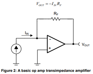
In order to see this low level current response, faster than the SMU can log in its buffer, we need a high precision op-amp to convert it to an appropriate amplitude voltage signal to input to our scope. The existing measurement circuit lends itself more favorably to a low-side sensing scheme, but a new one could be constructed if this community thinks high-side sensing is a better route, based on the experiment I've described. Bi-directional current sensing is preferred, and the ability to offset the output to center the response would be beneficial. The scope input sensitivity is about 1 mV/div, so we'd ideally like to see hundreds of mV to a couple V at the amplifier output.

I am completely new to analog circuit engineering, and this is my first time having to crowdsource from a pool of engineers who know better, instead of dealing one-on-one with an AE. Hopefully the information I've provided is a good enough starting point.

  • Kevin,

    The limiting value for your situation will be how small the input bias current (Ib) needs to be. Our devices have a small amount of current flow into both inputs of our devices that can cause errors when measuring small current values. Typically, these are on the order of µA, but the device with the smallest Ib is the INA190 with a bias current as low as 500pA. If you are looking to measure 10nA on the peaks and about 50pA steady-state this will mean 5% error on the peak magnitudes, and 1000% error during steady-state, so I would recommend you instead use an instrumentation amplifier which has a much lower input bias current.

    I will assign this thread to the team responsible for instrumentation amps for you after posting.

    Levi DeVries

  • Hi Kevin

    Because the source voltage has to remain around 15 V, and the DUT resistance is in the hundreds of GOhm, we end up with currents on the order of 10s of pA at steady state, to 10ish nA as a response to the pulsing "voltage steps."

    One of our new ultra precision op amp is OPA928, which the common mode input voltage can handle up to 16V, see the link below.  If the dipolar organic chromophores cell is maintained at 15Vdc across the top and bottom electrodes, you may input the cell's output current into a transimpedance amplifier (TIA), where input-current to output voltage is measured or current-to-voltage converter. This circuit is extremely precise to measure the current from the cell, and you should see very low %error measurement measurement with the converter. The TIA circuit is typically used to convert light (photons) to voltage via photodiode detector.  

    https://www.ti.com/lit/ug/tidu535/tidu535.pdf?ts=1681852486356&ref_url=https%253A%252F%252Fwww.google.com%252F

    If you are able to provide me with the DUT's input characteristics, such as input capacitance, output current range (min to max), step frequency responses, output voltage level, DC or AC or both measurements, I can simulate the condition for you. 

    Below is a simulation example of the mentioned in step response in the DUT (speculation in what you are trying to do). 

    OPA928 TIA step Response.TSC

    If you'd like to keep the proprietary product information, you may apply for "friendship" inquiry via E2E, where we have a private E2E messaging support forum or we can exchange the tech. information via our internal email as well. Please let us know. 

    Best,

    Raymond

  • Based upon the responses so far, I'll add a couple notes to clarify the purpose of the experiment, and the range of conditions we're hoping to test:

    1. The chromophores developed to date have always needed a constant poling field applied over the temperature cycle so as to lock their alignment in place. What we *do* know is that stepping up the poling voltage gradually, say 1 V at a time, results in current transients that spike positive when ramping voltage positive, and negative when ramping back down. What we *don't* know, is how the material will react to any temporary loss in applied voltage, as encountered when switching relays, and what effects this may have on their subsequent performance in the as-poled device; we want to simulate the behavior of pulsing the voltage from poling level to 0 V. Eventually, we might like to include some LC filtering elements in the poling circuit to stifle these current transients, but that is a subsequent experiment.

    2. I chose one set of conditions to illustrate our basic experiment, but in reality, we want to be able to amplify the current over a broader range of poling fields, up to on the order of 300 V/um or even higher. This means we need to be able to source voltage anywhere from 0 - 45ish V. The hope was that the components and circuit build would be low enough in cost as to perform several iterations for different material/device combinations, and that the conditions mentioned in the original post were simply meant to give us a starting point.

    @Levi Devries, that's a great point about input bias current, and an IA might indeed be what we're looking for here. Any more input you have to offer in that regard would be much appreciated.

    @Raymond Zhang1, I think I misunderstood the nature of TIAs from the start: doesn't the input need to be from an actual current source, rather than just the current flowing in the circuit across the DUT as a result of applied poling voltage? Yes, that simulation you posted is pretty similar to what we're trying to achieve! Unfortunately, I don't have any of the characteristics you mention are required for simulation; the organic materials, in this particular device application, simply haven't been characterized in this fashion yet.

  • Hi Kevin, 

    Enclosed is another simulation per the chromophores device. OPA928 is the state of art ultra low Ib op amp, and it will work well for the application. 


    OPA928 TIA Chromophores 04182023.TSC

    up to on the order of 300 V/um or even higher.

    I believe that you are trying to characterize the chromophores device. Let assume that you are able to control the DUT's sandwich thickness, say 10nm or 1nm or 100s angstrom levels, then you are able to lower the the applied potential. You can control the sandwich thickness with precision glass beads or characterize the film thickness of the device (if this is solid state film stack), thus the applied cell potential won't be as high as it needs to. 

    We have other high voltage difference amplifiers and it may work with the high applied voltage when it comes to actual devices when you reached to the validation point. It may be a different current measurement circuit from the simulation above, we may be able to provide you with a solution when you reached at that point. 

    Regarding to the current characterization, I think that the application may be only interested in transient AC current responses (may be DC as well). If this is the case, we can resolve the high voltage common mode issues with the actual chromophores device.

    Below is OPA928EVM, which you may check out the configuration for the application. 

    https://www.ti.com/lit/ug/sbou282a/sbou282a.pdf?ts=1681859771896&ref_url=https%253A%252F%252Fwww.google.com%252F

    If you have additional questions, please let us know. 

    Best,

    Raymond  

  • Hi Raymond,

    Our devices are fabricated on-chip, so the electrode spacing is fixed. If we were to try the OPA928 or OPA928EVM, would we need to configure the circuit as a high or low-side measurement?

    We are very much interested in both the transient current response (and how we might eventually filter it out), as well as the DC current. In fact, we use the DC current as an indication of chromophore ordering during poling (i.e. the more aligned the molecules, the more current we see), which is critical to the ultimate device efficiency.

    Do you have any input as far as Levi's suggestion of using an IA is concerned, vs precision op-amp as you've suggested?

    Thanks,

    -Kevin

  • Hi Kevin, 

    Do you have any input as far as Levi's suggestion of using an IA is concerned, vs precision op-amp as you've suggested?

    Levi and I are all recommending low Ib analog front end (AFE), but TIA and Instrumentation amplifier (IA) have slightly advantages for low current measurements in this case. INA190 also implemented with zero-drift and other design advantages, and It depends on the application and %error requirements per your characterization requirements. 

    Since OPA928 can operate up to 16Vdc rail, I would keep the current measurement on the high side for now. If the Vcm mode voltage is high, then we may have to adapt to low side current measurements. I think that Levi is in current sensing application team. If the measured current is higher, then the current monitor products may work as well. In addition, some of the current products have wide Vcm range also. So we have to evaluate each application and case separately.  

    https://www.ti.com/lit/an/sboa374/sboa374.pdf?ts=1681860587579&ref_url=https%253A%252F%252Fwww.google.com%252F

    Another possible current measurement is Logarithmic amplifier, such as LOG114, which it has over 8 decades of current input dynamic range. Anyway, I am providing you with different ultra low current measurement techniques and you can decide how to proceed with the measurements. They have pros and cons when it comes to your current measurement applications.  

    https://www.ti.com/lit/ds/symlink/log114.pdf?ts=1681865889083&ref_url=https%253A%252F%252Fwww.ti.com%252Fproduct%252FLOG114

    If you have additional questions, please let me know. 

    Best,

    Raymond

  • Hi Kevin, 

    I am going to close this inquiry. If you have additional questions, please let us know. 

    Best,

    Raymond