This thread has been locked.

If you have a related question, please click the "Ask a related question" button in the top right corner. The newly created question will be automatically linked to this question.

XTR111: not able to source 20mA into a 500 ohm load

Part Number: XTR111

Issue:  XTR111 not able to source 20mA into a 500 ohm load

I have two designs 
Design A utilizes the MSOP-10 package - it IS able to source 20mA into a 500 ohm load

Design B utilizes the DFN-10 package - it IS NOT able to source 20mA into a 500 ohm load.

Design B can source into a 250 ohm load.

Design B input
VIn vs current

1.2v    5 mA
2.5v    10.28 ma
3.7v     11.3 mA   
 stalls at 11.3ma

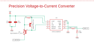
Both circuits have 2.49K set resistors

MSOP-10
works 250 or 500 ohm

DFN-10
250 ohm load - 0 to 20mA no issue
500 ohm load - stalls at 11mA  

I have checked - rechecked - tried several boards - the only common denominator is the XTR package.

Vin at VSP 20 Vdc no I limit on ps
Test circuit is XTR111 circuit output into 500 ohm load into mAMP meter to ground.
input pulled to gnd and +5

Design that does not work
Thanks

Carl

  • Hi Carl,

    The die the same for both devices, and the thermals are very close, so there shouldn't be any reason one part doesn't work.  

    I see one design above for the DRC package, is the design for the DGQ package the same?  Do you have the thermal pad undernieth connected to V-?

    The behavior you are describing would also align with the current limit circuit engaging on the MOS and pnp transistor.  Can you confirm the MOS/pnp/resistor are all the same values?

    Regards,
    Mike

  • both boards have thermal pads under part - 
    Both boards are machine built
    Both boards use the same transistor 
    Both boards use same 15ohm resistor
    They use two different PFETs - swapped problem design PFET onto good design board - and it worked fine.
    Swapped Good design PFET onto bad board - still did not work
     

    Yes both designs are the same - 
    Design that works has PS pulled high - because its not used - cut trace to float it - still worked

  • Just unsoldered XTR111 - has thermal pad with solder on it
    Just checked feedback resistor it is 15 ohm

  • Carl,

    I am looking into this as well.  The XTR111 should have compliance to Vvsp - 2V.  With a 500 ohm load your output should be about 5.5V @ 20mA on the load.  With a 20V supply you should have significant compliance margin.  The XTR111 EVM uses the DRC (DFN-10) package, and your circuit configuration looks fairly close to the EVM configuration.  At this point I don't see an obvious reason why your DFN circuit is not able to output 20mA (it should output up to 25mA).  I will take a closer look at this tomorrow.

    Question 2:  Did you purchase the DFN device from an authorized TI vendor?  We do occasionally see cases where counterfeit devices have limited functionality.   

    Questions 2:  You may consider probing all the pins with and oscilloscope to see if you have stable DC signals on each pin (e.g. no oscillations or cycling due to over temperature protection).  I don't necessary expect this, but it is always good to confirm that everything is stable DC.

    Thanks for your patience with this issue.  I hope we can help you to resolve the problem soon.

    Best regards,

    Art Kay

  • Hi MIke

    Thanks for looking into this
    I do not ask for help until I have exhausted all other options - this one has me stumped.

    I have check with our board vendor - they got the xtr111 from TI

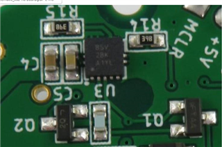
    Marking on part BSV 28K A1Y1 of boards that do not work.

    I have placed the sensor in the error mode and looked at signals I can reach with scope.
    FET Trans, Vin Rset and see no oscillations

    During our development phase - we hand built a board - and it worked 
    It had date code - BSV 15K COLY

    I am having 2 more hand built to test. - I could know later today

    Thanks
    Carl

  • I changed Rset from 2.49k to 1.25K 
    it used to stall at 3v in 11.4 mA out
    Now it stalls at 1.5v in 11.4 mA out
    Kind of what I expected it its current limiting on the output

  • We are also putting a xtr111 from our inventory on a production bad board to see if it fixes it

  • Carl,

    This is a good plan.  I'll get an XTR111EVM on order so that I can run experiments on our side and confirm specific operation against signals on key pins.  Based on your comments, the device may be defective.  It will be interesting to see how the circuit works with the new device.

    Art

  • I think I have an unconnected ground plane on my board - am not sure - as I have not found it yet - but if I cut the 5v ps connection I have voltages where they do not belong. I have to get with out board guy - and have him check it out - Its so spooky it's driven me crazy. So for now I would thank you and just wait - 
    Carl

  • Carl,

    Thanks for the update.  Best wishes on a quick resolution.

    Art

  • Morning Art

    It is a board error - the output is wrapped back into the micro and exceeding the input range

    Thanks for you time

    Carl