Other Parts Discussed in Thread: LAUNCHXL-F28379D
Hello,
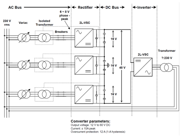
We are building a lab setup for testing and using the board BOOSTXL-3PhGaNInv as rectifiers in the setup illustrated below.
The system will be composed of three two-level three-phase converters operating as a rectifier connected in series.

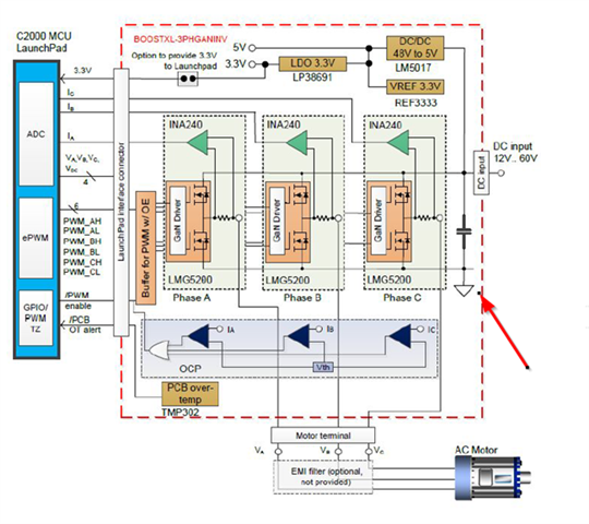
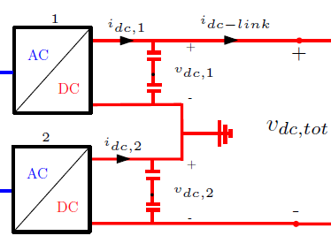
The system has a floating-point voltage on the DC link of each converter and we are gonna split the capacitor, so we have a mid-point in each converter, where the mid-point of the middle converter is grounded. However, according to the schematic of the BOOSTXL-3PHGANINV, the power ground and signal ground are connected. This poses an issue for us, because we don't want the signal ground which is connected to the microcontroller (LAUNCHXL-F28379D) to have a voltage potential. Due to the risk of possibly destroying the microcontroller and connected PC.

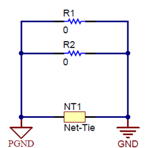
Would it be possible to operate the system by disconnecting the signal ground from the power ground on the DC bus on the inverter board? We already removed the two resistances shown in the schematic below. The only way to open the net-tie would be to remove the copper trail from the board? Would there be any problems for the board if we do that? Is there anything else we can do to disconnect both grounds?

I appreciate the help in advance. Let me know if you have any questions.
P: I don't know if this qualifies in the right forum, let me know if you need to change the forum


