This thread has been locked.

If you have a related question, please click the "Ask a related question" button in the top right corner. The newly created question will be automatically linked to this question.

INA333-Q1: The INA333 output changes opposite to the input

Expert 1045 points
Part Number: INA333-Q1
Other Parts Discussed in Thread: INA333, OPA320

Hi team,

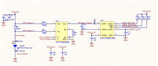
I am using INA333 for current sampling. The hardware Settings are as follows. The power supply of INA333 is +3.3V and -1V respectively.
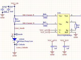
When I increase VCC_LD, the voltage at both ends of R61 increases, but the output value of INA333 decreases.
When I reduced VCC_LD, the voltage at both ends of R61 decreased, and the output value of INA333 increased. This is contrary to the intention of the design. May I ask what causes this result?

  • Hi Suy,

    I am clear that the INA333 supplies are +3.3V and -1V respectively.  However, I have a couple of questions to help debug the issue:

    - What is the VCC_LD supply voltage range on the above at the high-side of the Rshunt 10mΩ resistor?  

    -  If possible please provide the LD940 laser diode datasheet, Or, please let us know what is the operating voltage and intended forward current range for the laser diode? 

    - What circuit is driven by the INA333?  Are you using a meter or oscilloscope to measure the INA333 output?  Is there any capacitive load at the INA333 output that could cause instability? Please show in the diagram what circuit is connected at the INA333 ouput.

    - Is the issue occurring on one INA333 PCB board, or several devices?  

    Thank you and Kind Regards,

    Luis  

  • Hi Luis  ,

       Let me answer a few of your questions:

       1,the VCC_LD supply voltage range is 1~3V

       2,Now I have not welded the 904 LD. The current test uses a power resistor of 1ohm instead (rated at 50W).

       3,The output of the INA333 is a differential ADC (model ADS7039QDCURQ1) with no capacitive load. I used an oscilloscope to test the output of INA333. It is a relatively stable voltage, and the ripple vpp is about 30mV.

      4,At present, there is only one PCB. I am not sure whether all the PCBS are OK, and I have replaced the new INA333. In addition, please note that the Rg of INA is currently set at 5k instead of 20k.

  • Hi Suy,

    1) Are you performing the measurements with an external voltage meter or are you currently using the ADC for the measurements on the evaluation? If using the ADC, can you please probe the INA333 output with an external meter? 

    2) What is the max sampling rate required in the application?  Please note the ADS7039 is a SAR ADC that can sample up to 2-MSPS.  The INA333 is a relative low-bandwidth instrumentation amplifier and will not be able to drive the sample-and-hold at high sampling rates without a buffer amplifier.

    3) Does the 10mOhm shunt provide sense connections?  If you wish to provide the PCB layout Gerber plots, we will happy to review.

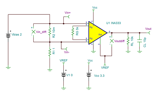
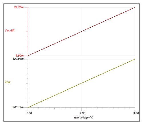
    Below is a quick simulation using TINA, with 1-Ohm power resistor, 10mOhm shunt resistor.  Performing a DC sweep of Vbias from 1V to 3V provides the expected linear output.

    Thank you and Regards,

    Luis


  • Hi Suy,

    The INA333 is a high DC precision device with low power consumption and relative low bandwidth in the few 10s of kHz. If you require to sample at high sampling rates, you will need to buffer the instrumentation amplifier. 

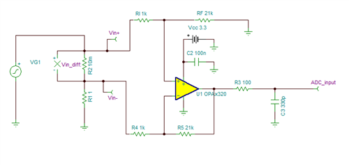
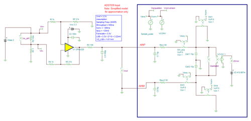
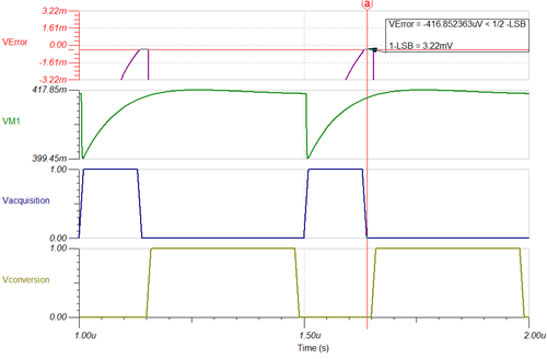
    If you require to sample AC signals with higher Bandwidth, you may require a higher bandwidth amplifier. One possible solution is below, using the OPAx320-Q1 in a difference amplifier configuration on a gain of 21x.  The OPA320 has a GBWP of 20-MHz can drive the 10-bit SAR ADC at full throughput. TheOPAx320-Q1 configured in the difference amplifier circuit below on G=21x, has a bandwidth around ~975-kHz and can drive the ADC at full-throughput of 2-MSPS.

    Thank you and Regards,

    Luis 

  • Hi Luis,

       I am very sorry that I forgot to reply you because of the Labor Day holiday. Your suggestion was very good, but finally I found that the chip did not work properly, which led to such a situation. After I replaced a new INA333, the circuit worked normally. I really appreciate your reply.