This thread has been locked.

If you have a related question, please click the "Ask a related question" button in the top right corner. The newly created question will be automatically linked to this question.

INA226-Q1: INA226-Q1 measurement current was less

Part Number: INA226-Q1
Other Parts Discussed in Thread: INA226

Hi, Support Team

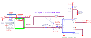
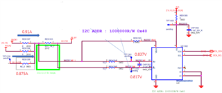
We calculator total current is 3.3A, but we measuring current is 1.785A. ( Rshunt is 0.001ohm)

below as schematic:any something wrong?

0.875A+0.91A=1.785A...

TPT1301:0.837V

TPT1302:0.817V

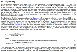
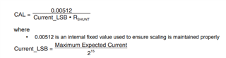
Q1: According our circuit the maximum expected current is 10A?

Q2: why meascument current only 1.785A?

if any suggestion, Please advise me.

Thanks,

Best regards,

Lawrence

  • Lawrence,

    Could you clarify for me what the problem you are encountering is? Are you measuring a current with the INA226 you don't expect? It would be helpful if you could repeat what the expected maximum current is, the shunt resistor value, and the calibration value you used to program the device.

    It looks like you also posted some values for the pin voltages, but the values on the schematic don't match what you wrote. Did you measure these values when the output was 1.785V?

    Levi DeVries

  • Hi, Levi

    Are you measuring a current with the INA226 you don't expect?

    Yes. According schematic we expect maxumum current is 10A, but we measuring current only 1.785A. 

    It looks like you also posted some values for the pin voltages, but the values on the schematic don't match what you wrote. 

    repost schematic.

    Did you measure these values when the output was 1.785V?

    Yes. output was 1.654V/1.785A

    if any suggestion, Please advise me.

    Thanks,

    Best regards,

    Lawrence

  • Hi Lawrence & Levi

    1. I corrected the value of Rshunt, from the circuit diagram, Rshunt is 0.01 ohms


    2. Then the main problem at present is that we are not sure how much Maxmun Expected Current should be set, and whether there is a reference way to decide how much this value should be set to.

    Thanks

  • Hi, Guys

    According equation 1 and 2.

    base on Rshunt is 0.01ohm

    CAL=512; Current_LBS=1mA/Bit

    The Maximum Expected Current is 2A. am i right?

    if any suggestion, Please advise me.

    Thanks,

    Best regards,

    Lawrence

  • Lawrence,

    we are not sure how much Maxmun Expected Current should be set, and whether there is a reference way to decide how much this value should be set to.

    The source of your confusion seems to be the calibration process, so I will go over it briefly. The Maximum Expected Current and the Shunt Resistance are the inputs determined by your application.

    The first value you should calculate is the Current LSB from the maximum current you want to measure. For measuring 10A you will use 10A/215 = 305µA. From this value you can calculate CAL, which will be 0.00512/(0.3mA*10mΩ)=1677. Is this the value you used when programming the device?

    When reading from the device, you must multiply the Current LSB by the value of the current register to find the real current value.

    The schematic you posted looks good to me, but the measured values are slightly off. You are expecting 10A, but only measure 20mV instead of 100mV, indicating 2A of current across the shunt resistor. Additionally, you labeled the current on the branches as 1.785A total, which is also inconsistent with the 2A.

    Hopefully fixing the calibration process can fix your issue however,

    Levi DeVries